Structure and function
24 Dok-ID:EXPERT-0003-EN-2011
Pos: 4.16 /S martT ur n/S mar tTur n-Neu-0 2.2 011/ 4.2. 5 G erät eei nst ellu ng S te uer einh eit-S 1 @ 2\ mod_1296813371510_38.doc @ 25924
4.2.7 Device settings - control unit
There are three setting possibilities on the control unit, S1, S2,
and S3. They are behind a screw-fastened cover.
S1 Settings mode – lock angle drive roller.
S2 Reset system faults
S3 Rotary direction, clockwise rotation – counter-clockwise
rotation, drive roller
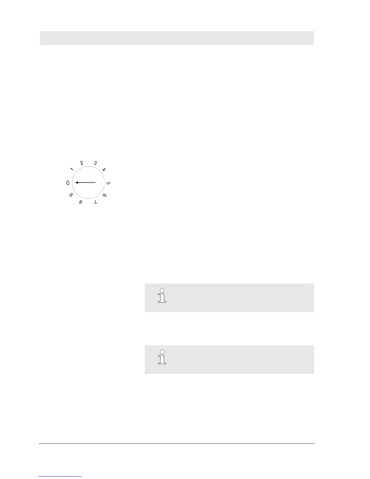
S1: Settings mode and lock angle
Rotary switch
Fig. 5 Rotary switch – S1g
0 No function
1 Standard mode with 20° lock angle
2 Standard mode with 30° lock angle
3 Standard mode with 40° lock angle
4 Standard mode with 60° lock angle
5 No function
6 No function
7 No function
8 No function
9 Standard mode with 30° lock angle
Use the rotary switch to set the respective lock movement of the
drive roller.
When commissioned in the factory the drive roller is set
appropriately. The default value is position 2 = 30 degrees.
Settings other than positions 1-4 and 9 have no function. The
settings of S1 and S3 must be marked on the inside of the cover.
NOTE!
If the device is replaced the value must be set
appropriately.
Pos: 4.17 /S martT ur n/4. 2.5 _a G erät e eins t S2 @ 1\ mod_1219400981074_38.doc @ 7240
S2 Reset system fault
Use the button to reset system faults on the device.
NOTE!
Additional instructions on fault rectification are
provided in the section -> System faults.