Structure and function
28 Dok-ID:EXPERT-0003-EN-2011
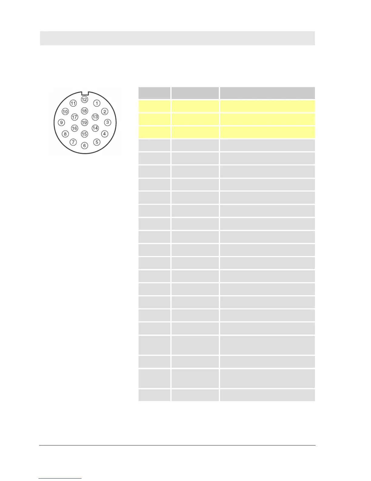
4.3.1.1 Pin assignment control unit
X1 – PLC interface
Fig. 9 Pin assignment control unit – X1
Pin Pin assignment Function
19 24V 24 V DC supply
6 0 V Reference potential
12 PE Protective conductor
1 NC
2 NC
3 NC
4 NC
5 E3 Input slow on
6 0 V Reference potential
7 E4 Input mode
8 A3 Output 0-position
9 A4 Output overrun forward
10 A5 Output overrun backward
11 A6 Output system fault
12 PE Protective conductor
13 A7 Output end lock angle
14 A8 Output position front
15 A9 Output position back
16 E5
Special mode pre-select cycles bit
1
17 A10 Sensor in the lock angle
18 E6
Special mode pre-select cycles bit
2
19 24V 24 V DC supply