Turntable control SmartTurn
Structure and function
Dok-ID:EXPERT-0003-EN-2011 29
Pos: 4.23 /S martT ur n/S mar tTur n-Neu-0 2.201 1/4.3. 1.1_ a Pin- belegung Steuerungseinheit @ 3\mod_1296815568589_38.doc @ 26001
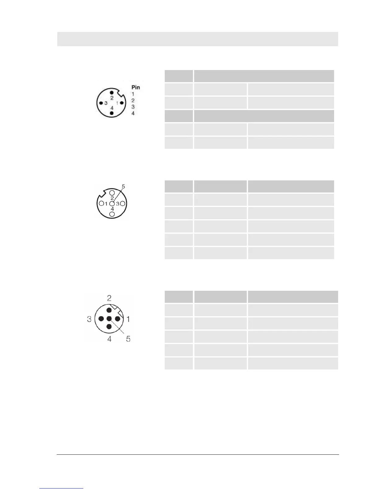
X2 – inputs/outputs power unit
Fig. 10 Pin assignment control unit – X2
Pin Inputs
1 E1 Forward on
3 E2 Backward on
Pin Outputs
2 A1 Forward start
4 A2 Backward start
X3 – sensor interface
Fig. 11 Pin assignment control unit – X3
Pin Pin assignment Function
1 24V 24 V DC supply
2 T+ Cycle input
3 0 V Reference potential
4 T- Cycle input
5 X NC
X4 – Diagnostics interface (RS232)
Fig. 12 Pin assignment control unit – X4
Pin Pin assignment Function
1 RxD RxD
2 NC NC
3 TxD TxD
4 NC NC
5 GND GND
Pos: 4. 24 /Smar tTur n/4.3. 2 Ansc hlüss e-Sens or @ 1\mod_1219305984027_38.doc @ 7140