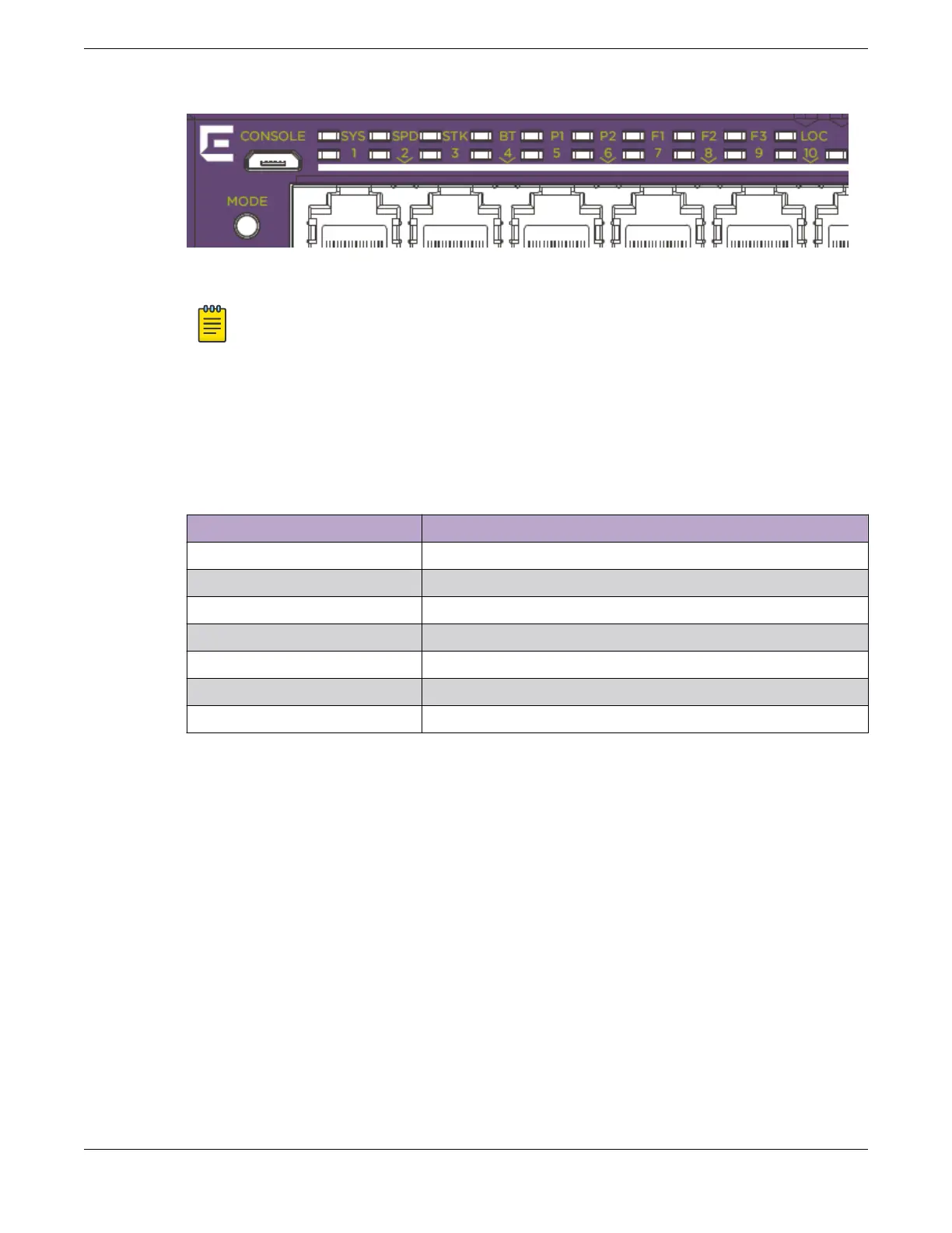
Figure 88: 5520 Series Mode and System Status LEDs
Note
Front-panel PoE ports use Amber to indicate PoE states.
Port LEDs in Default (SYS) Mode
In the default SYS mode, SPD is OFF, and the port status will display behavior for link, trac, and PoE as
described in the following table:
Table 28: Port LEDs in SYS Mode (default)
Color/State Meaning
Steady green Link is OK; port is not powered
Steady amber Link is OK; port is powered; no trac
Blinking green Link is OK and transmitting packets; port is not powered
Blinking amber Link is OK and transmitting packets; port is powered
Slow blinking amber No link, or disabled port; port is powered
Alternating amber and green Port has a power fault
O Port is not powered, has no link, or is disabled
Port LEDs in SPD Mode
After one press of the Mode button, the port LEDs will enter the SPD Display Mode, indicated by the
SPD LED. SPD mode is used to help determine the operational speed of a port.
There are two LEDs per QSFP28 port on 5520 models. In stack mode, the first LED will represent the
link state and trac of the stack port with solid or blinking green. When a QSFP28 port is used for
Ethernet and partioned to 4x10 or 4x25, one LED will be shared for two ports. The first LED will indicate
state for the first two ports and the second LED will indicate state for the second two ports. The LED is
on or blinking green to indicate link and trac when any of the 2 ports are up. It is o when both ports
are down. In partitioned 2x50, each LED will represent link and trac for one 50G port. In aggregate
Monitoring the Device
Port LEDs in Default (SYS) Mode
ExtremeSwitching 5520 Series Hardware Installation Guide 125
 Loading...

