The rear panel of the switch includes:
• 2 fan modules
• Grounding lug
• 1 Type-A USB port
• 2 power supply slots
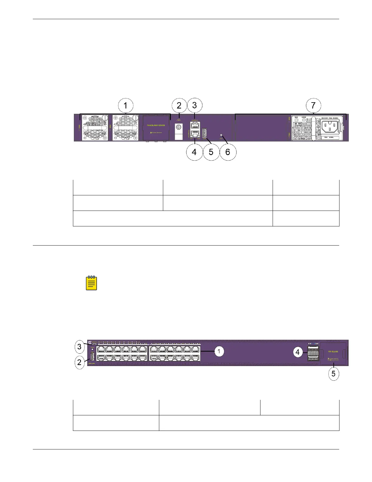
Figure 2: 5520-24T Rear Panel
1 = Fan modules 3 = Serial console port 5 = USB 2 port
2 = Grounding lug 4 = OOB management port 6 = Locator LED
7 = Power supply slots
5520-24W Switch Features
The front panel of the 5520-24W switch includes:
• 24 10/100/1000Mb full/half duplex MACsec capable ports with 802.3bt Type 4 PoE (90W)
Note
Half-duplex is not supported on these ports when operating at 1Gbps.
• 1 VIM slot
• 1 Type-A USB port
• 1 Micro-B USB console port
• 2 Stacking/QSFP28 ports
Figure 3: 5520-24W Front Panel
1 = 10/100/1000Mb ports 3 = Micro-B USB console port 5 = VIM port (covered)
2 = USB 1 port 4 = Stacking/QSFP28 ports
ExtremeSwitching 5520 Series Overview 5520-24W Switch Features
ExtremeSwitching 5520 Series Hardware Installation Guide 15
 Loading...

