IPCP Pro Series • Hardware Features and Installation 39
Digital output — To activate LEDs, incandescent lights, or other devices that accept
a TTL signal, or to provide contact closure control for projector lifts, motorized screens,
room or light switches via an Extron IPA T RLY4 or similar device, you can use one or
more of these ports as a digital output. When a port is configured for digital output, it
offers two output states: on and off.
• When the port is set to an “on” state, (the switch 1 circuit is closed), the I/O pin is
connected to ground. Output voltage is less than 0.5volts.
• When the port is set to the “off” state (the switch 1 circuit is open), the output pin
floats (is not connected).
• If the application calls for TTL compatibility, the digital output circuit can be set up
to provide a 2kohm pull-up resistor to +5VDC, which you can use if the connected
device does not provide its own power.
• If the pull-up resistor is disabled, voltage output is determined by an external
source device.
• If the pull-up resistor is enabled, switch 2 is closed, voltage output is 4.3VDC.
Each I/O port is capable of accepting 250mA, maximum.
• Digital I/O digital output with pull-up disabled
• When switch 1 closes, the port is on and the front panel LED is on.
• When switch 1 opens, the port is off and the front panel LED is off.
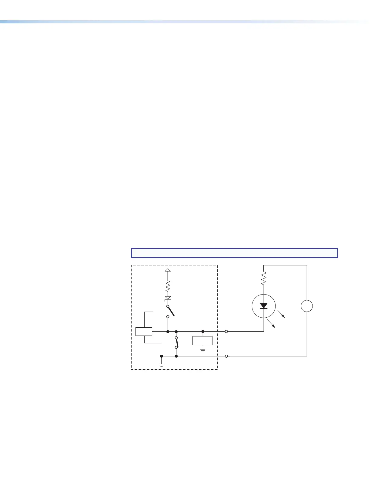
• Example application, digital output without pull-up: connecting an LED
and an external +5VDC power source
This application often requires a current-limiting resistor, as shown in the
diagram below. Many button switches that contain LEDs have a resistor built in.
See the guide for the lighted switch or stand-alone LED for details.
NOTE: Each flex I/O pin is capable of sinking a maximum of 250 mA.
+
-
+5.0 V
1k ohms
SW 2
SW 1
Digital
I/O
GND
Voltage
Protection
CTL
LED
Externa
+5 VDC
Power
Source
Resistor
(R)
Figure 36. Digital I/O Digital Output Application:
LED and External +5VDC Power Source Without Pull-up