IPCP Pro Series • Hardware Features and Installation 40
To determine the value of the current limiting resistor in the circuit shown above,
you need to know the values of three variables:
i = LED forward current in amps (found in the data sheet for the LED)
V
f
= LED forward voltage drop in volts (found in the data sheet for the LED)
V
s
= supply voltage of the external voltage source
Insert those values into the following equation to determine the resistor value:
s
f
Example calculation:
i = 5 mA (0.005 A)
V
f
= 2 V
V
s
= 5 V
NOTE: If the value calculated for the current limiting resistor is not a
standard resistor value, you can round up the number to the next highest
common resistance value.
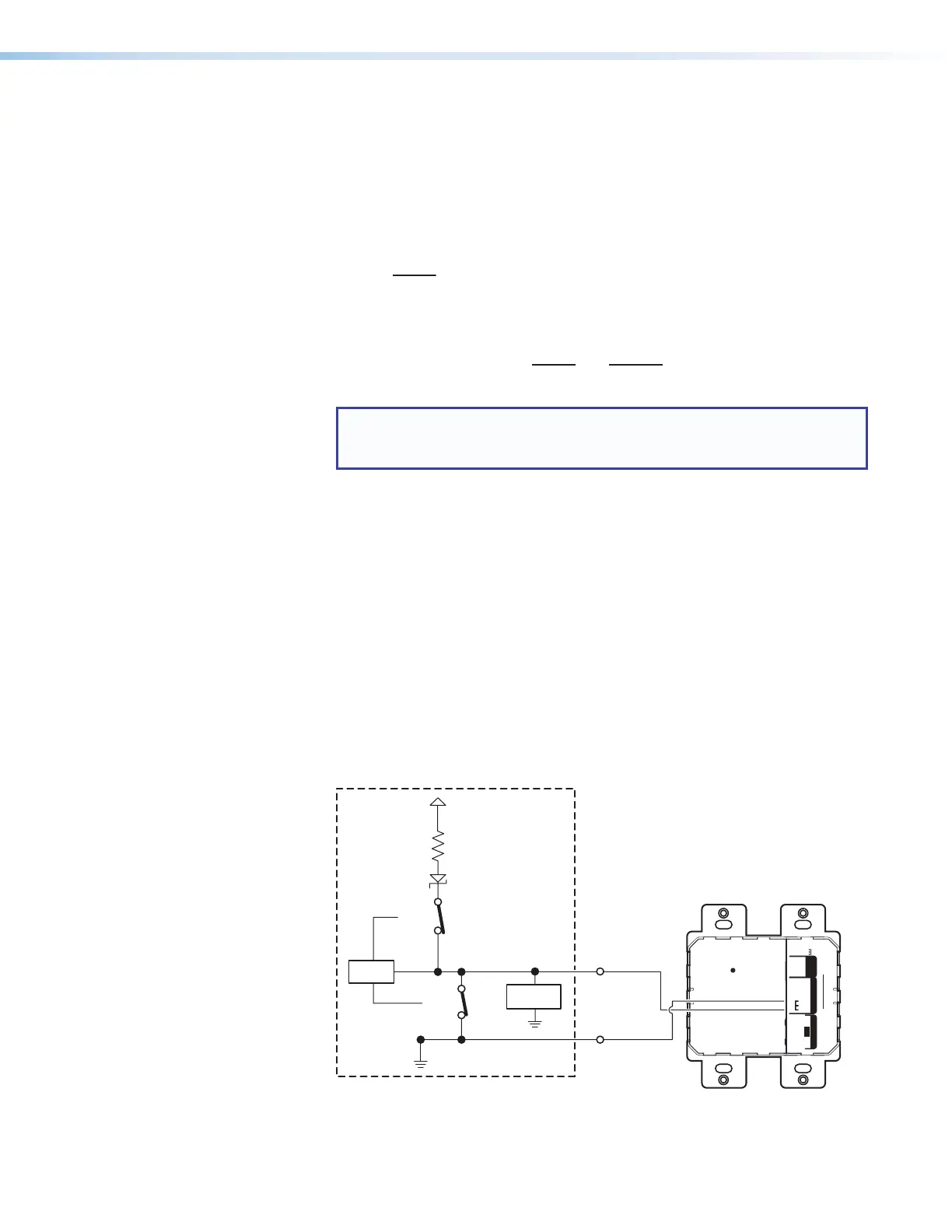
The connected LED is off when the port and switch 1 are open.
The connected LED is on when the port and switch 1 are closed.
• Digital I/O digital output with pull-up enabled
• When the port is configured for pull-up, switch 2 is closed, activating the
+5.0VDC pull-up resistor.
• When switch 1 closes, the port is on and the front panel LED is on.
• When switch 1 opens, the port is off, and the front panel LED is off.
• Example application, digital output with pull-up: controlling another device
via its contact closure input port
Connect the digital I/O port to the contact input port of another device, such
as an Extron DTP transmitter. When activated, the digital I/O digital output port
momentarily shorts pin 1 to ground (pulsed contact for 0.5seconds), closes
switch1, which selects the input on the connected device.
R
DTP OUTREMOTEOVER
DTP
SIG LINK
RS-232
CONTACT
DTP T UWP 232 D
Tx Rx
Tx Rx G
POWER
12V
A MAX
- -
+–
G1 2
A/S
+5.0 V
1k ohms
SW 2
SW 1
Digital
I/O
GND
Voltage
Protection
CTL
DTP T UWP 232 D
Figure 37. Digital I/O Digital Output Application With Pull-up:
Contact Closure Input Selection on a Connected Device
}
=
=
s
f