IPCP Pro Series • Hardware Features and Installation 42
This port provides power to eBUS devices. If the power draw by the connected
devices reaches the maximum level allowed, the eBUS Limit LED lights. If the power
consumption exceeds the allowed threshold, the IPCP shuts off the eBUS port and
lights the eBUS Overload (Over) LED. If that occurs, you must resolve the hardware
cause of the power overload before the IPCP can successfully restore function to this
port. Once the power consumption of the port is reduced to below the maximum
overload condition threshold, the eBUS port automatically re-enables and resumes
function.
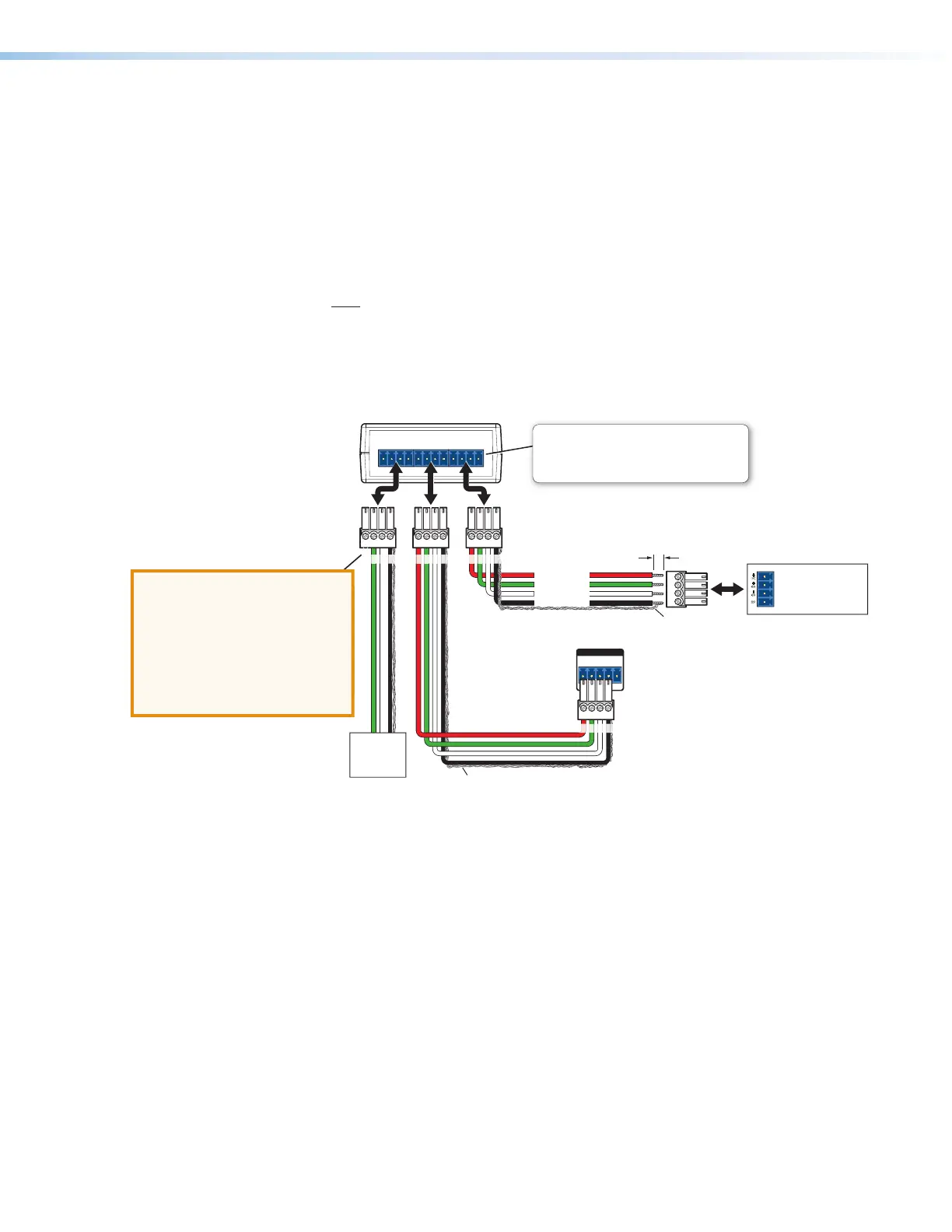
If additional power supplies are required for an eBUS system, consider the following:
• Do not connect power from both the IPCP and the supplemental power supply to
any eBUS device.
• Do not allow power from the supplemental power supply to flow to the IPCP.
See the following diagram as an example of a system where both an IPCP and a
supplemental power supply are included in the eBUS topology.
+
V G
-
S
+
S
+
V G
-
S
+
S
+
V G
-
S
+
S
eBUS DISTRIBUTION HUB
PWR OUT = 6W
-S+V +S G
eBUS
IPCP Pro
Rear Panel
+
V
+
S G
–
S
eBUS port on an
EBP or other
eBUS device
G
-
S+S
+V
Tie drain wires to ground.
X
G
-
S+S
G
-
S+S
Tie drain wires to ground.
G
-
S
+S
+V
+ Signal
-
Signal
+12 VDC
Ground
G
-
S+S
+V
G
-
S+S
+V
Powered
eBUS
device(s)
eBUS Connections
• Connect up to four (4) eBUS devices to the
eBUS distribution hub (EBDB MINI).
• Wire the connectors the same at both ends.
ATTENTION: Do NOT
connect the power pin
to any device that is
already powered by the
IPCP Pro control
processor or by an
addi tional power supply.
ATTENTION:
• Do NOT connect the power pin to
any device that is already powered
by the IPCP Pro control processor
or by an additional power supply.
• NE connectez PAS la broche
d'alimentation à un appareil déjà
alimenté par le processeur de
contrôle IPCP Pro ou par une autre
source d'alimentati on.
3/16" (5 mm) Max.
EBDB MINI
Rear Panel
(or use
an EBDB
10-port hub)
Figure 39. Connecting eBUS Devices in a System With Both an IPCP and
Another Powered eBUS Device
3/30/17: peer reviewer for rev. E asked
if these bulleted lines of eBUS wiring
advice should be attention notices.
Per John Spencer, 4/21/17: “Nothing will
happen to the product or the user if
wired wrong, other than it wont work.
So no, lets not change it “
Rev. G, 7/2018:
Added French text
to the eBUS wiring
Attention notice.