Quantum Series Videowall Processing Systems • QC 101 Controller 71
H
HDMI output connector — (Optional) Connect an external display that supports
HDMI to this connector for use when configuring a Quantum processor using the
Quantum Configuration Software.
NOTE: The LED and recessed button labeled Reset are not functional on this
product.
Installation Overview
Follow these steps to install and set up the QC 101 to control a Quantum videowall
system:
1. Disconnect power from all equipment.
2. (Optional) Mount the unit to a rack or furniture, following the instructions provided with
the mounting hardware (see Mounting the QC 101 on page 80).
3. Connect a display to the VGA, HDMI, or DisplayPort output connector (see figure 59,
B
,
E
, or
H
on the previous page) to use while creating configuration projects for
the Quantum.
4. Connect the keyboard and mouse (or a keyboard and mouse combination) to one or
both of the USB connectors (see figure 59,
C
) to use while creating configuration
projects using the Quantum Control Software. If desired, connect a flash drive to
either USB port to store the projects you create.
5. Connect a straight-through Ethernet cable between one of the QC 101 LAN ports
(see figure 59,
D
) and the network or the Quantum rear panel Control connector.
If connecting through a LAN, ensure that the QC 101 and all Quantum processors
are on the same subnet. See Ethernet Connections on page 51 for information on
wiring Ethernet cables.
6. Connect a control device (such as an Extron IPL Pro control processor) to the Remote
RS-232 port (see figure 59,
F
) for remote control of the Quantum system via R-type
commands. See Connecting for RS-232 Control on page 72 to connect to this
port. See the Quantum Control Software User Guide, available at www.extron.com,
for a list and description of the available R-type commands.
7. Connect AC power to the QC 101 rear panel IEC connector. Connect power to all
other devices in the system.
8. Power on the Quantum chassis and all other connected devices.
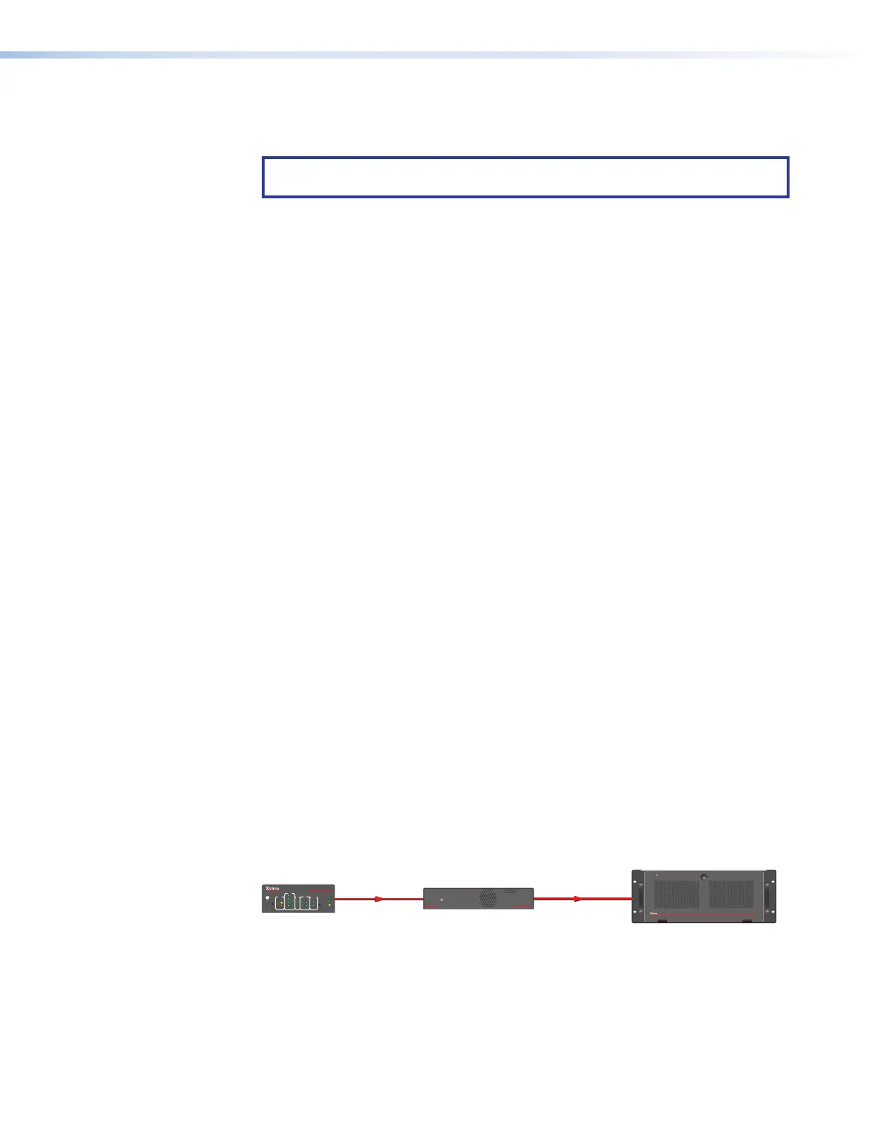
Connectivity Options
Using a straight-through cable, you can connect the QC 101 to a Quantum processor by
either of the following methods:
• Directly from a QC 101 LAN port to the Quantum Control connector on the rear panel
(see figure 60).
RS-232
QC 101
Controller
Quantum Connect
E
PWR
SSD
QUANTUM CONTROLLER
QC 101
LAN A
LAN B
CONFIG
QUANTUM CONNECT 408
VIDEO WALL PROCESSOR
DATA
Ethernet
1000
LINK
ACT
R
IR
IPCP PRO 250
eBUS
OVER
LIMIT
S
COM
I/O
1
2
2
4
1
321
RTS
CTS
Tx
Rx
RELAYS
IR/S
Control
System
Figure 60. QC 101 Direct Connection