FSG 90 System
3 Installation
16 FAV_D10024 December 2014
only to sine wave testing. It will be therefore higher than the usual 2% ... 10% sinus
modulation distortion, but will stay far below the maximum allowed 25% modulation
distortion factor with sinus modulation.
6. Therefore, evaluation of the effectively occupied total transmitter band width
(spectrum mask) is the only true, real measurement method. Such measurements
can be made only with specific test set-up.
7. For tests of the FSG 90(X) modulation capability, a sine modulation signal is useful
only below some 70% AM depth, and is on the other hand helpful only in determining
of possible overmodulation, but is not applicable to judge "voice distortion" anymore.
18
5
6
4
1
13
2
14
17
7
23
11
12
10
25
3
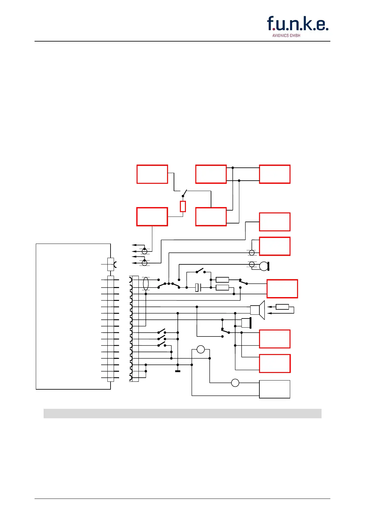
Amplified/Carbon Microphone
Dynamic Microphone (HI)
Dynamic Microphone (LO)
AF External
Loudspeaker OUT
Power Ground
Headphone (HI) OUT
Microphone GND
Push-to Talk Switch
Intercom
Display Lighting (HI)
+13.8 Vdc Power
+13.8 Vdc Power
Display Lighting (LO)
Power Ground
Headphone (LO) OUT
Distortion
Analyzer and
Millivolt Meter
Power Supply
13.8/14.0 Vdc
at least 5 A
VHF Signal
Generator
R&S, SMG
Dynamic microphone/s or
amp/carbon microphone/s
Equivalent
resistor
4 / 5 Watt
Transmitter Check
Receiver Check
> 15 W
Dummy load,
if required
DO NOT wire other
pins than noted!
Always turn OFF the radio first before connecting or disconnecting the D-SUB connector
Fig. 3-1: FSG 90 System
Test Set-up