FSG 90 System
3 Installation
December 2014 FAV_D10024 25
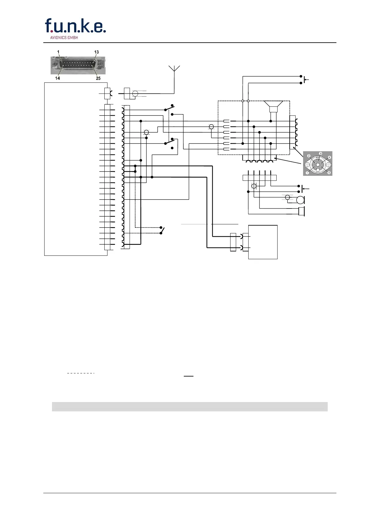
A/C Speaker out
Headphone (HI) out
Headphone (LO) out
AF External
Dynamic Microphone (HI)
Dynamic Microphone (LO)
Intercom
RTS
RxD
Display Lighting LO
+13.75 V A/C Power
+ 13.75 V A/C Power
Power Ground
Microphone GND
RX Signal
AF Sum
PTT Switch
Amp/Carbon Microphone
AF Modem out
CTS
Data Ground
TxD
+13.75 V Lighting HI
Switched 13.3 Vdc OUT
Power Ground
1
2
3
4
5
6
7
8
9
10
11
12
13
14
15
16
17
18
19
20
21
22
23
24
25
Dimmer or lighting
switch
(not included in wire
harness)
A/C Power
Supply
Lead-Calcium
Battery
12 V/ 7.2 Ah
e.g. F10382
A/C Speaker
10 W/4 Ω
A/N F10061
Stick PTT switch/es
(as required)
To connect a 2
nd
dyn. hand-held
microphone with
PTT switch or a
2
nd
headset
PTT Switch
(as required)
Dynamic
Microphone
Headphone
(as required)
#18-#20 AWG
0.6-0.75 mm²
red
#18-#20 AWG
0.6-0.75 mm²
blue
Headset or hand-
held dynamic
microphone with
PTT switch
NOTES:
DO NOT wire other pins than noted!
Unless otherwise noted, all wires are #22 AWG (0.3 -0.4 mm²).
Intercom operation requires a microphone, which provides audio OUT with the PTT key
de-energized (not keyed).
Built-in circuit breaker when using f.u.n.k.e. Battery A/C Power Supply, A/N F10382.
Length of pre-fabricated wire harness F10190: 2.9 m/ 9.5 ft.
and coax antenna cable are not included in wire harness F10190!
Always turn OFF the radio first before connecting or disconnecting the D-SUB connector
Fig. 3-6: FSG 90 System
Hook-up Diagram using wire harness F10190
1 - 2 Dynamic Microphone(s) and Intercom