FSG 90 System
3 Installation
26 FAV_D10024 December 2014
13.75 V Lighting HI
from Dimmer or
lighting switch
A/C Speaker out
Headphone (HI) out
Headphone (LO) out
AF External
Dynamic Microphone (HI)
Dynamic Microphone (LO)
Intercom
RTS
RxD
Display Lighting LO
+13.75 V A/C Power
+ 13.75 V A/C Power
Power Ground
Microphone GND
RX Signal
AF Sum
PTT Switch
Amp/Carbon Microphone
AF Modem out
CTS
Data Ground
TxD
+13.75 V Lighting HI
Switched 13.3 Vdc OUT
Power Ground
1
2
3
4
5
6
7
8
9
10
11
12
13
14
15
16
17
18
19
20
21
22
23
24
25
A/C POWER
13.75 Vdc/
14.0 Vdc
*Built-in stick
PTT switch
Pilot
Amplified/Carbon
microphone *with
PTT switch
A/N E08639
Headphone
Jack
JJ-034
Microphone
Jack
JJ-033
A/N E08640
Headphone Plug PJ-055
A/N E08941
Microphone Plug
PJ-068, A/N E08942
Copilot
Amplified/Carbon
microphone *with
PTT switch
A/N E08639
Headphone
Jack
JJ-034
Microphone
Jack
JJ-033
A/N E08640
Headphone Plug PJ-055
A/N E08941
Microphone Plug
PJ-068, A/N E08942
1 or 2 A/C speaker
4
to
AF External input
e.g. COM 2, NAV, MKR
Audio OUT to Audio Panel
(as required)
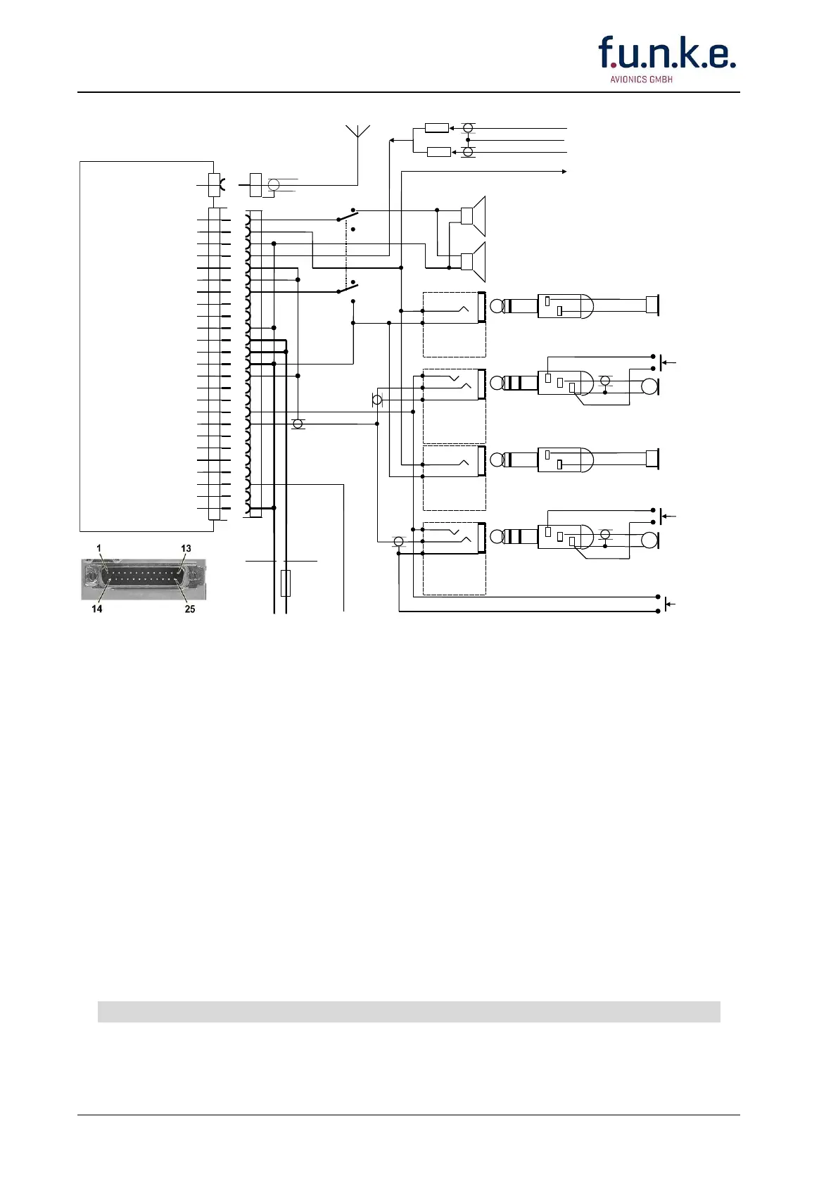
NOTES:
DO NOT wire other pins than noted!
Unless otherwise noted, all wires are #22 AWG (0.3 -0.4 mm²).
Unless otherwise noted, all Power Grounds are airframe grounds.
Intercom operation requires a microphone that provides audio OUT with the PTT key de-
energized (not keyed).
Intercom operation requires a selector switch, double pole, double throw.
Terminate audio shields at one end only.
Mount the Power bus circuit breakers in the A/C breaker panel or instrument panel such
that they will be accessible in flight and safe from physical damage.
* PTT Key/s either at hand-held microphone/s or installed on the yoke.
Wiring without Intercom: connect A/C speaker direct to pins 1 and 3.
If more than one AF source isolation resistors 470 Ohm shall be installed.
6 W model: Fuse 3.15 Amp quick acting, or circuit breaker 3 Amp.
10 W model: Fuse 5 Amp quick acting, or circuit breaker 5 Amp.
Always turn OFF the radio first before connecting or disconnecting the D-SUB connector
Fig. 3-7: FSG 90 System
Hook-up Diagram
2 Amplified/Carbon Microphones
and Intercom