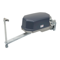
INSTRUCTION MANUAL MT, MA2, MK2, M10 DRIVE UNIT
17
• Technical specification
Electric motors
e design, rated output and connection dimensions of the motors meet the requirements contained in Swedish and
European Standards according to IEC 31-1 and 72 together with SS4260101 and SS4360102.
Ratings for motor types used in the MT:
Motor type
~
Hz
Output
kW
Voltage
V
Current
A
Motor
speed
rpm
Type of
opera-
tion*
Ingress
protection
rating
Thermal switch
SKg 63-2B
3-phase
50 0.25
220-240 D
380-420 Y
1.1-1.2
0.65-0.72
2760
S1 IP55
With or without a
thermal switch**
60 440-480 Y 0.65-0.72 3310
STKg 63X-4C
3-phase
50 0.25
220-240 D
380-420 Y
1.65-1.8
0.95-1.0
1400
S1 IP55
With or without a
thermal switch**
60 0.30 440-480 Y 0.95-1.0 1680
SEMKg 63-2B
1-phase
8uF/450V
50 0.18 240 1.45 1360 S1 IP55
With or without a
thermal switch**
SEMKg 63-4C
1-phase
8uF/450V
50 0.18 240 1.70 2760 S1 IP55
With or without a
thermal switch**
*S1 = Continuous operation. e motor can be subject to full load in continuous operation.
*S3 = Intermittent operation. e motor must not be subject to full load for more than 25% of the 10 minute duty cycle.
In practice the motor is not subject to full load for more than one second just as it starts.
**e motor is available both with and without an integrated thermal switch. If the motor has a thermal switch there is a
red label on the motor indicating this.
Gears
Select the opening speed taking account of the size and weight of the gate. e basic rule is to select a lower speed for large
gates.
WARNING
Too high an opening speed can result in trapping forces being too
large despite the use of a sensing strip.
ELECTRIC MOTOR
OUTPUT SPEED
rpm
GEARING
i
MOTOR SHAFT
SPEED
rpm
TORQUE
Nm
OPENING TIME
seconds
1400 750 1,90 550 16
2800 750 3,80 275 8
• Installation and commissioning
General installation
WARNING
Always start installation with a run through of the points in the:
"Pre-installation checklist".
WARNING
e drive unit must be installed so that no unprotected moving
parts are lower than 2,500 mm.
WARNING
Always use the fasteners prescribed in the assembly drawing with
regard to: property class, dimensions, length and quantity.

 Loading...