Do you have a question about the Fargo DTC1250e and is the answer not in the manual?
| Print Technology | Dye-Sublimation / Resin Thermal Transfer |
|---|---|
| Print Resolution | 300 dpi |
| Card Capacity | Input Hopper: 100 cards; Output Hopper: 30 cards |
| Card Sizes | CR-80, CR-79 Adhesive Back |
| Connectivity | USB 2.0 |
| Memory | 32 MB RAM |
| Card Thickness | 9 mil to 40 mil |
| Operating System Support | Windows 7, 8, 10 |
Overview of the service manual's purpose and scope for technicians.
Critical safety instructions for handling printer components and performing repairs.
Lists essential tools needed for printer repair and replacement procedures.
Step-by-step guide for safely removing printer covers for access.
Steps to remove covers from the DTC4500e lamination module.
Procedure for completely removing the lamination module from the printer.
Procedures for replacing the printer's main logic board and display assembly.
Steps to replace key motors, belts, and rollers like stepper motor, mag roller, and output roller.
Procedures for replacing Encoder, Ribbon, and Card Path/Cover sensors.
Procedures for replacing the flipper cover and flipper table assembly.
Steps to replace flipper feed rollers, gears, and stepper motor.
Procedures for replacing the lamination module's mainboard and head assembly.
Procedure for removing and replacing rollers within the lamination module.
Detailed procedure for replacing the printer's printhead assembly.
Diagrams showing mainboard connections for printer and lamination module.
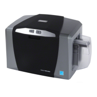
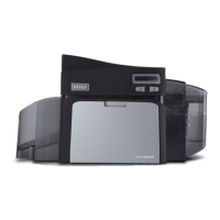
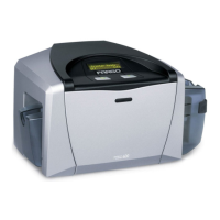
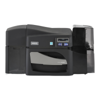
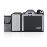
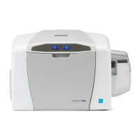
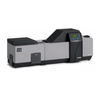
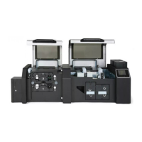
Visual representations of printer components and their assemblies.