FaroArm User Guide
January 2007
13
Chapter 1: Introduction to the FaroArm
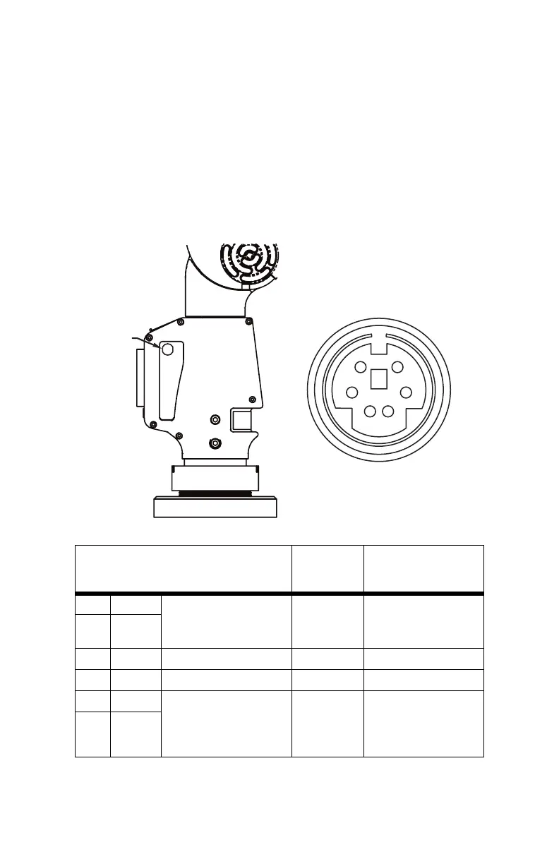
Auxiliary Port (7th Variable Options Port)
On the side of the FaroArm base, a communications port is available to
connect external equipment.
W
ARNING: Only use FARO approved devices in this port. Using
other devices could damage your system and will void your
maintenance/warranty service plan.
Figure 1-9 Auxiliary Port
Pin
#
Signal
Name
Description
Signal
Direction
Comments
1 Trigger + The Trigger signal is used to
force the FaroArm to
immediately issue a Capture
signal.
From External
interface to
FaroArm.
RS485 differential signal.
If (Pin 2 > Pin1 by 200mv)
then the FaroArm will
initiate a capture.
2 Trigger -
3 GND Logic Ground N/A Connect to Ground
4 NC No Connect N/A Do Not Connect
5 Capture + The Capture signal
acknowledges that a Trigger
signal has been received and
records the current position of
the FaroArm.
From FaroArm
to External
interface.
RS485 differential signal.
When (Pin 6 > Pin5 by
200mv) then the FaroArm
has initiated a capture.
6Capture -
Table 1-2 Auxillary Port Pins
AUXILIARY
PORT
12
34
56
08M46E00_FaroArmUSB.book Page 13 Monday, January 15, 2007 1:12 PM