Do you have a question about the Faro Edge and is the answer not in the manual?
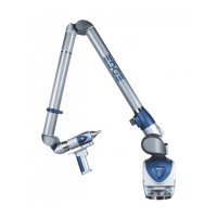
Describes the 7-axis articulated arm, encoders, base assembly, communication ports, and probe end assembly.
Provides FCC and Industry Canada compliance statements for wireless components.
Explains WEEE directive and product disposal guidelines for European Union countries.
Lists precautions for using the Edge, avoiding solvents, abuse, moisture, power fluctuations, and temperature changes.
Lists standard items shipped with the Edge system, including shipping case and accessories.
Describes the process of setting up the Edge, including mounting the base.
Explains how to mount the Edge base to a stable surface using threaded rings and plates.
Details the procedure for attaching and tightening probes using a wrench.
Explains the location and functions of the fold-down touch screen controller.
Covers power supply specifications, voltage tolerance, and connection.
Provides instructions on how to carefully pack the Edge for shipping.
Describes the meaning of different LED colors and states on the handle.
Instructions on how to reference the seven encoders in the Edge for accurate measurement.
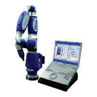
Discusses PC compatibility and communication protocols (USB, Ethernet, Bluetooth, WLAN).
Covers connecting the Edge to a computer using wireless options.
Describes the Bluetooth connection, pairing process, and data transfer rates.
Provides background information on WLAN, IEEE 802.11 standards, and network types.
Describes the standard 6mm and 3mm ball probes and how to enter their exact diameters in software.
Introduces the optional FARO i-Probe, its features, and activation process.
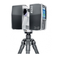
Explains the non-contact laser line probe, its operation, and computer requirements.
Details laser safety precautions and warnings for the FARO Laser Line Probe.
Explains the necessity of probe compensation and the procedure involving the Compensation Plate.
Details settings for the FARO Laser Line Probe, including scan rate, density, and exposure.
Defines compensation and calibration concepts for measurement equipment like the Edge.
Explains factory compensation procedures and conditions that may invalidate it.
Describes software commands for testing accuracy and repeatability using holes, ball bars, or gauges.
Discusses how loss of a degree of freedom can affect measurement accuracy.
Provides general maintenance guidelines for the Edge and Host Computer.
Explains how to test the mounting stiffness to ensure optimal performance.
Information on ESD, its effects, and procedures to follow if an error occurs.
Addresses common problems like error messages and probe compensation failures.
Troubleshooting communication problems between the Edge and the host computer.
Identifies factors affecting accuracy, including mounting, compensation, probes, and measurement environment.
Describes the elements at the top and bottom of the Edge software screen.
Outlines the six groups of commands available in the Edge software's main menu.
Use of commands in the Construct menu for Part Setup, Lengths, Angles, and Features.
Creating a coordinate system and aligning it to the part using the Right-Hand Rule.
Using feature commands to construct exact or best-fit features.
Using commands in the Measure menu for features, lengths, and angles.
Storing measurement steps, nominal values, pictures, and part data in files.
Explains the Device Control panel for configuring devices and viewing properties.
How to change the probe via the Probe Management button in the Device Control panel.
Compensating the probe using the Probe Compensation Point button.
Compensating the probe using the Probe Compensation Sphere button.
Changing the Edge setup through the Hardware Configuration button.
Accessing Edge diagnostics through the Diagnostics button.
Explains the Device Control panel in CAM2 Q for configuring devices.
How to change the probe in CAM2 Q via Probe Management.
Compensating the probe in CAM2 Q via Probe Compensation Point.
Compensating the probe in CAM2 Q via Probe Compensation Sphere.
Changing Edge setup in CAM2 Q via Hardware Configuration.
Accessing Edge diagnostics in CAM2 Q.
Setting up the primary input device in CAM2 Measure.
Configuring hardware settings like trigger mode, stress stops, and mouse control.
Managing probes, including compensating, viewing logs, and enabling i-Probes.
Procedure to compensate the probe for accurate measurements, with Hole and Sphere methods.
Performing Hole Compensation using the probe cone with guidance.
Detailed steps for performing Hole Compensation using the probe cone.
Detailed steps for performing Sphere Compensation using a precision sphere.
Displays compensation history and allows setting to active or deleting previous compensations.
Using diagnostics menu to test mounting, accuracy, temperature, and environment.
Displays current temperature and sampling time, advising steady state before measuring.
| Brand | Faro |
|---|---|
| Model | Edge |
| Category | Measuring Instruments |
| Language | English |