FARO Edge
September 2012
104
Chapter 7: Software
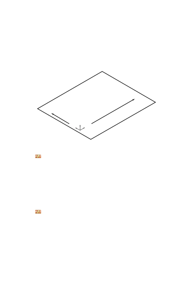
Plane Line Line
From the MAIN menu, touch CONSTRUCT > PART SETUP > PLANE LINE
LINE. Use this command to create a coordinate system on your part.
The plane defines the XY plane, the first line defines the X-Axis, and the
intersection of the first and second lines defines the origin of the coordinate
system.
1 Choose an existing plane in the P
LANE drop-down list or touch the MEASURE
NOW icon to measure the plane:
• Place the ball probe on the part and digitize points by pressing the GREEN
button. You must digitize at least three points for a plane. Hold the RED
button to remove any unwanted points.
• Pull away from the face, and press the RED button to define probe
compensation and complete the measurement.
• Look at the plane results. Press the GREEN button to accept, or the RED
button to reject and remeasure.
2 Choose an existing line in the L
INE drop-down list or touch the MEASURE
NOW icon to measure the first line:
• Place the ball probe on the part and digitize points by pressing the GREEN
button. You must digitize at least two points for a line. The first two points
define the direction of the line. Hold the RED button to remove any
unwanted readings.
• Pull away from the edge, and press the RED button to define probe
compensation and complete the measurement.
• Look at the line results. Press the GREEN button to accept, or the RED
button to reject and remeasure.
Figure 7-7 Plane Line Line part setup
X
Z
Y
08M52E00_FaroArm_Edge.book Page 104 Thursday, October 4, 2012 9:31 AM