FARO Edge
September 2012
58
Chapter 4: Probes
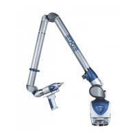
Holding the FARO Laser Line Probe
Never grab the FARO Laser Line Probe while measuring. Simply hold the Edge's
pistol grip.
N
OTE: Avoid touching both lenses. Clean the left and right lenses with the
cloth from the FARO Laser Line Probe Case. Dirt and grease on either lens can
cause poor results.
Hardware Controls and Indicators
The Edge/FARO Laser Line Probe system uses the FRONT (Green) and BACK
(Red) and the Handle LEDs.
Buttons
Use the buttons on the Edge handle or the buttons on the FARO Laser Line Probe
handle to control measuring.
• Use the FRONT (green) button to start data collection. Points are only sent to
the computer when the laser is in range. Once you start collecting data, press
the FRONT button again to pause.
• Use the BACK (red) button to end any measurement command.
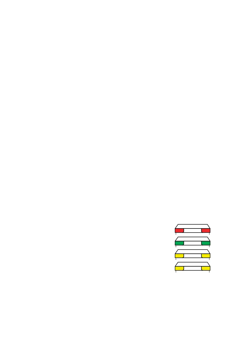
LEDs
The two Handle LEDs, indicate the distance to the target object from the FARO
Laser Line Probe. Remember, data is only sent to the computer when the FARO
Laser Line Probe is in range.
• Out of Range (two Red LEDs). The Laser Line Probe is too
close or too far from the part.
• Center Range (two Green LEDs) The Laser Line Probe is in
the center of the range.
• Near Range (two Yellow LEDs) The Laser Line Probe is in
range, closer to the part.
• Far Range (two Yellow LEDs) The Laser Line Probe is in
range, farther from the part.
Additionally, the software uses the Range Finder dialog box to show the distance
and position from the FARO Laser Line Probe to your part.
08M52E00_FaroArm_Edge.book Page 58 Thursday, October 4, 2012 9:31 AM