FARO Edge
September 2012
137
Chapter 7: Software
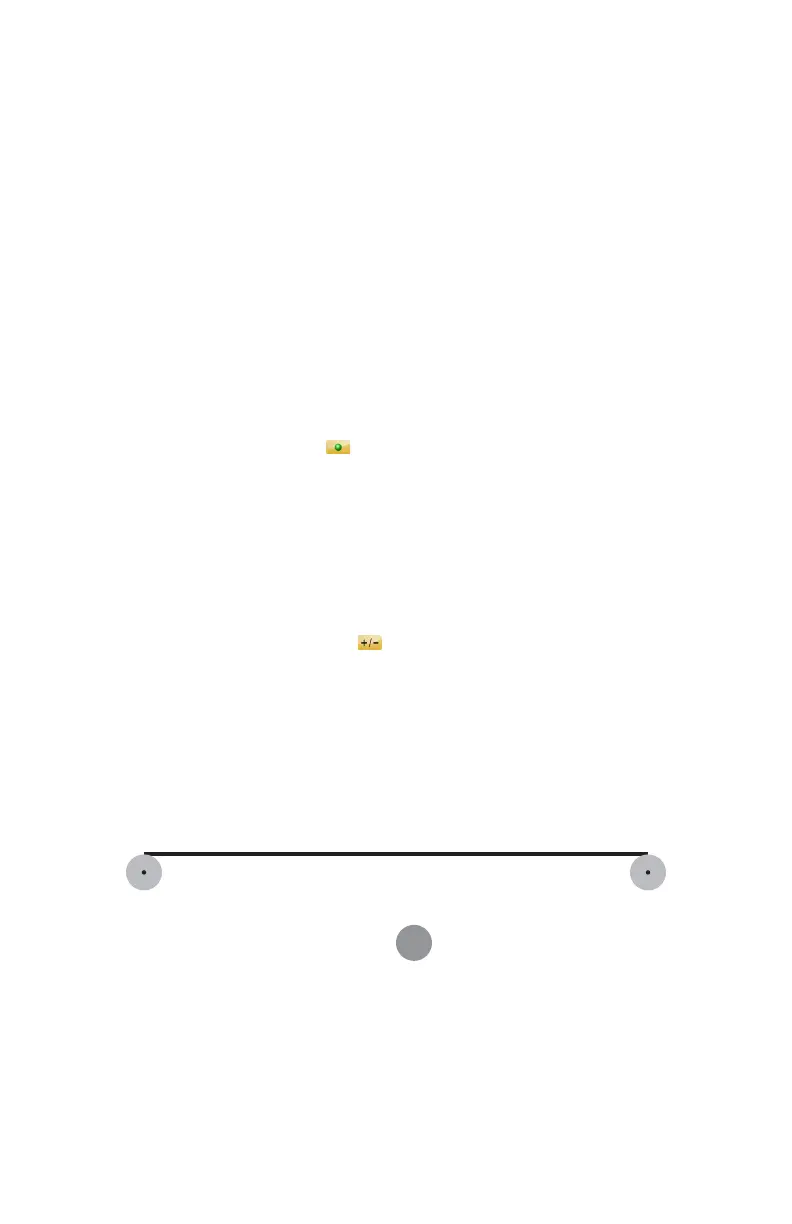
Line
From the MAIN menu, touch MEASURE > FEATURES > LINE. Use this
command to measure straight edges. You must record at least two points to solve
the line.
• Choose an existing plane, or New to measure a plane. The digitized points are
projected to the plane before the best-fit calculation. If no plane is available
then measure a plane. See “Plane” on page 138.
• Measure the line:
• Place the ball probe on the part and digitize points by pressing the GREEN
button. You must digitize at least two points for a line. The first two points
define the direction of the line. Hold the RED button to remove any
unwanted readings.
N
OTE: Touch the SCAN icon to enable scanning. When enabled, press
and hold the GREEN button to collect points as you touch and move the
probe across the part. For more information, see “Application” on
page 151.
• Pull away from the edge, and press the RED button to define probe
compensation and complete the measurement.
• Look at the line results. Press the GREEN button to accept, or the RED
button to reject and remeasure. Touch the L
ABEL field to change the feature
name. Touch the NOMINALS icon to enter nominal values. See
“Nominals” on page 143.
N
OTE: If you measured a new plane in this feature command and rejected
the line results, the plane remains in the file. Delete any unwanted features
using the REVIEW FEATURES command. See “Review Features” on
page 143.
You can continue and measure another line, or press the RED button to cancel the
command.
See “Best Fit Line” on page 167.
Figure 7-17 Measure Line
08M52E00_FaroArm_Edge.book Page 137 Thursday, October 4, 2012 9:31 AM