TST_FUxF-A-C-F_Montageanleitung_EN_15
3 Safety functions in accordance with EN 12453:2017
EN 12453:2017 places special requirements on safety-related signals. These signals must comply
with a minimum of PL “c”, cat. 2 in accordance with EN 13849-1. To guarantee these safety
requirements, the complete chain of sensors, actors and if necessary, the wiring must be taken into
account accordingly. This affects (amongst others):
• Path restriction units (limit switch)
• Actuators with automatic reset
• Slack rope switch
• Slip door switch
To comply with these standard requirements, these signals can be connected via the Emergency-
Stop inputs of the controller (terminal no. 31-32 and 41-42).
Alternatively, standard digital inputs can be used. In this case, an additional output must be
configured as a test output and integrated in the signal chain.
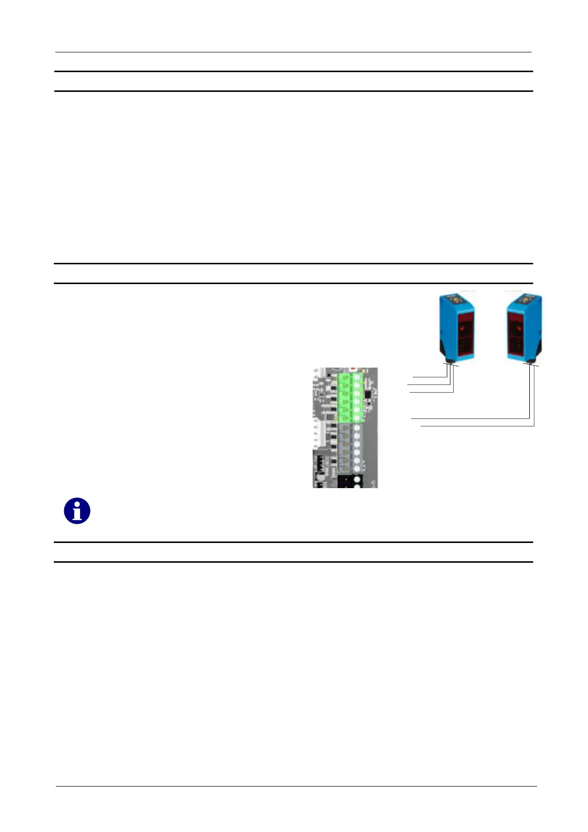
3.1 Connection example testing
In this example, the testing is described using
a transmitter-receiver light barrier.
The transmitter is supplied with 24 V via a
test output.
In a test case, the output is switched off so
that the transmitter is voltage-free.
The receiver now switches the input.
The controller checks whether the input really
switches and switches back.
If YES, the test was successful, if NO, error
F.928 is set.
76 - +24 V
75 - IN 5
74 - GND
73 - +24 V
72 - IN 4
71 - GND
66 - OUT 15
65 - IN 10
64 - IN 9
63 - GND
62 - +24 V
61 - IN 8
Empfänger
Receiver
Sender
Transmitter
Both digital outputs and relays can use used as a test output.
3.2 Parametrization
To activate the function testing, inputs and a relay must be configured for testing.
1. Input configuration P.5xA:
P.5xA = 0: No testing activated
P.5xA = 1: Testing the input upon reaching the end position OPEN and after activation
P.5xA = 2: Testing the input upon reaching the end position CLOSE and after activation
X = Number of the input to be configured
2. Configuring the output P.7x0:
P.7x0 = 17: Testing in end position CLOSE
P.7x0 = 25: Testing in end position OPEN
The relay is energized when the test is inactive
X = Number of the input to be configured
 Loading...