TST_FUxF-A-C-F_Montageanleitung_EN_15
14 Specifications
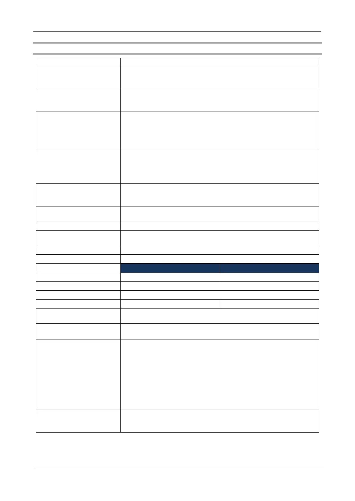
approx. 195 x 270 x 150 mm to frame with quick release
incl. heatsink
excl. extension boards as TST RFUxK or TST RFUxCom
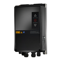
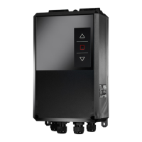
Dimensions plastic housing
approx. 210 x 430 x 200 mm
incl. heatsink, brake resistor & wall mounts
excl. cable entries (L +20 mm) and main switch (H+ 35 mm)
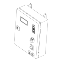
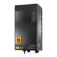
Dimensions inside the steel
or stainless steel housing
approx. 300 x 476 x 218 mm (Typ: SG / EG)
approx. 400 x 676 x 218 mm (Typ: SGG / EGG)
approx. 600 x 676 x 218 mm (Typ: SXG / EXG)
excl. cable entries (L +20 mm) , main switch and emergency
stop button (H+ 35 mm)
Hygiene housing
dimensions
(TYP: HZG)
approx. 375 x 540 x 251 mm
excl. cable entries (L +20 mm) , main switch and emergency
stop button (H+ 35 mm)
Hygiene housing
dimensions
(TYP: HYG)
approx. 444 x 549 x 210 mm
excl. cable entries (L +20 mm) , main switch and emergency
stop button (H+ 35 mm)
Electronics and cooling as are assembled for low-vibration and
vertical mounting, e.g. on a suitable masonry wall.
Screws on the cover of
plastic housings
6x Phillips PZ2 stainless steel (A2)
Torque: max 1 Nm
Knob, lockable, assembled on DIN rail
Protection K-characteristic
Power consumption
controller without drive
max. 140 W with full utilization of 24 V supply
External supply 1
(X10: L '/ N'):
Transmission of phase L1 and N.
L' is protected on the circuit board: 4 AT
Control voltage /
External supply 2
(a.o. Terminal ”+ 24V": 51,
62 ,73, 83 , 91 .“GND“: 35,
63, 71, 74, 81, 84, 94, 36*,
44)
24 V
DC
C ± 5 % max. 3,500 mA protected extra low voltage
according to EN 60335-1
• incl. all external loads such as plug-in modules, I/O
modules, 24 V brake, switched transistor outputs and more
control voltages
• Short-circuit protected by central switching regulator.
• GND potential internally grounded to PE.
• If the FU3F is supplied with mains voltages below 300 V, the
max. load of the 24 V supply is only 2.5 A.
Control voltage / External
supply 3 (Terminal 33, 45 -
Pay attention to Jumper)
For electronic limit switches and Safety edge
Nominal value 11.5V / max. 130 mA
 Loading...