3 Safety functions in accordance with EN 12453:2017
EN 12453:2017 places special requirements on safety-related signals. These signals must comply with a
minimum of PL “c”, cat. 2 in accordance with EN 13849-1. To guarantee these safety requirements, the
complete chain of sensors, actors and if necessary, the wiring must be taken into account accordingly. This
affects (amongst others):
• Path restriction units (limit switch)
• Actuators with automatic reset
• Slack rope switch
• Slip door switch
To comply with these standard requirements, these signals can be connected via the Emergency-Stop inputs
of the controller (terminal no. 31-32 and 41-42).
Alternatively, standard digital inputs can be used. In this case, an additional output must be configured as a
test output and integrated in the signal chain.
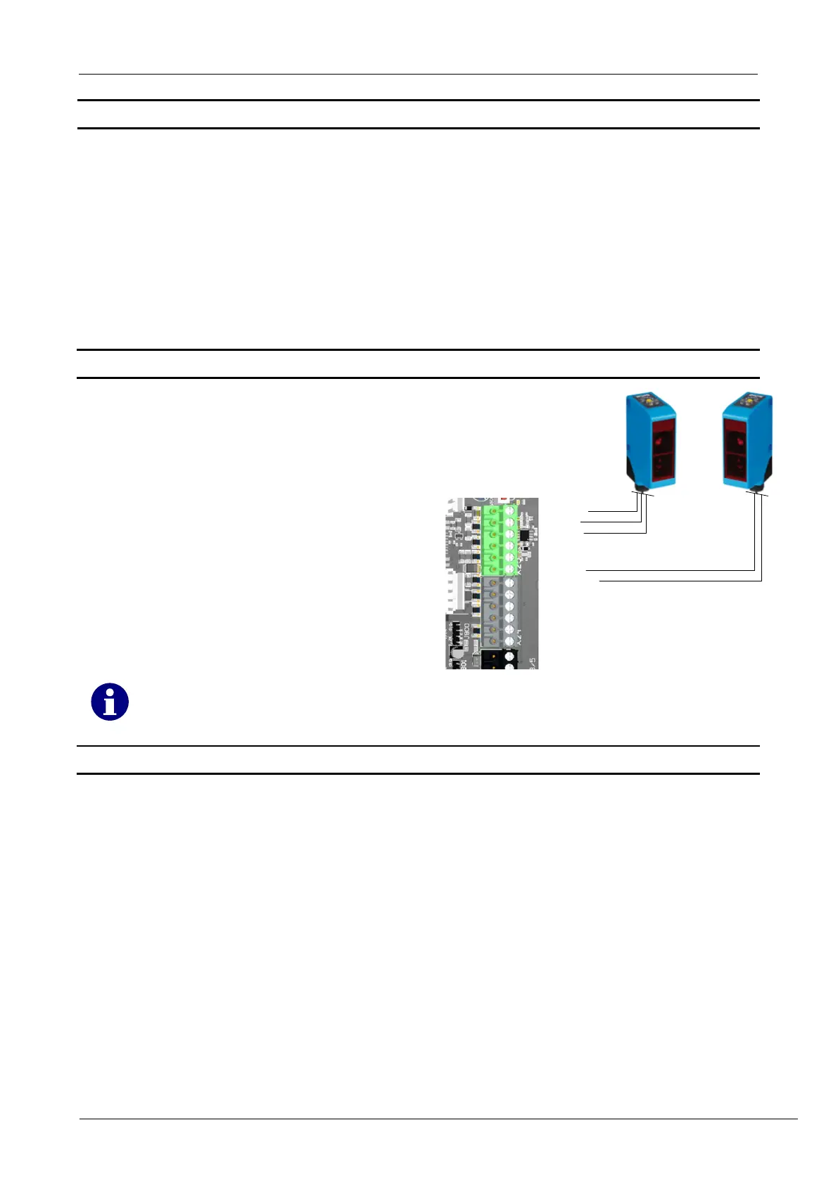
3.1 Connection example testing
In this example, the testing is described using a
transmitter-receiver light barrier.
The transmitter is supplied with 24 V via a test
output.
In a test case, the output is switched off so that
the transmitter is voltage-free.
The receiver now switches the input.
The controller checks whether the input really
switches and switches back.
If YES, the test was successful, if NO, error F.928
is set.
3.2 Parametrization
To activate the function testing, inputs and a relay must be configured for testing.
1. Input configuration P.5xA:
P.5xA = 0: No testing activated
P.5xA = 1: Testing the input upon reaching the end position OPEN and after activation
P.5xA = 2: Testing the input upon reaching the end position CLOSE and after activation
X = Number of the input to be configured
2. Configuring the output P.7x0:
P.7x0 = 17: Testing in end position CLOSE
P.7x0 = 25: Testing in end position OPEN
The relay is energized when the test is inactive
X = Number of the input to be configured
 Loading...