VEK MNH Operating Manual v1.3 en
10 Description of functions
In the following section the indicator and control elements are described.
Information in this document
This document refers to the default settings or default values defined by the manufacturer. The factory
settings of customer variants may differ from the manufacturer’s specifications. Please observe the
instructions on the device, as well as the documents supplied with it.
10.1 LED status indicators
The LEDs (light emitting diodes) on the front side indicate the state of the loops and the detector.
There are two LEDs for each loop channel:
• The red LED indicates the coverage status of the respective loop
• The blue LED indicates the operating status of the detector
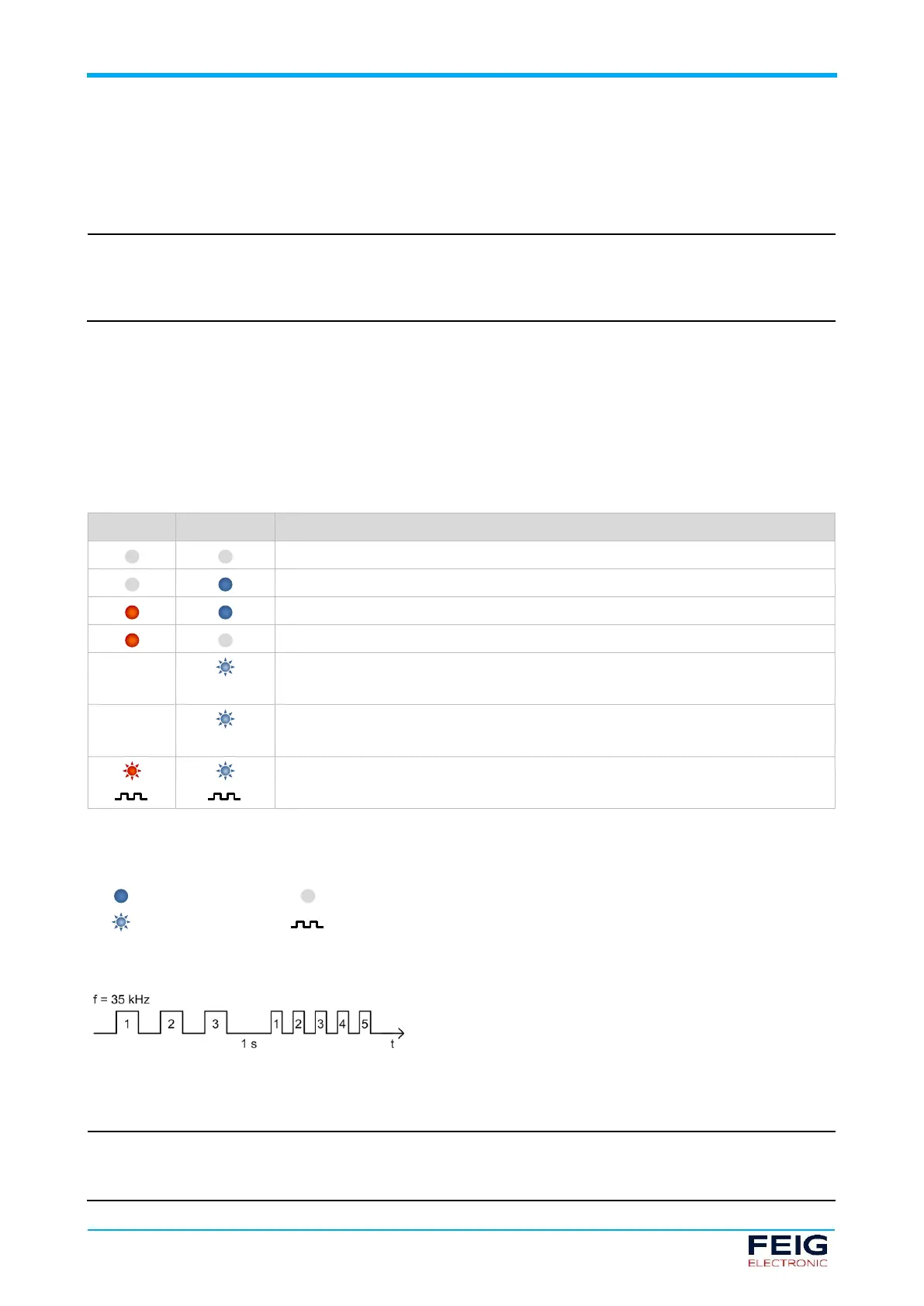
No power supply, detector inactive
Detector ready, loop connected, no object detected
Detector ready, loop connected, object detected
No loop connected, loop break, loop closure
Ready for operation following earlier, now rectified, loop error or
settings changed with Detector Tool (DIP switch not up-to-date)
Frequency alignment is running
After frequency adjustment, both LEDs simultaneously display the set loop
frequency in a flash code (see Flash code illustrated example)
Tab. 9: LED signal colours
Key to LED symbols
LED flash code following a frequency alignment
Fig. 8: LED display of loop frequency
LED position
The LEDs for the loop channel 1 are located at the top or side of the device, for loop channel 2 are in the
middle.
 Loading...