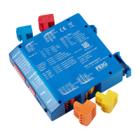
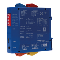
VEK MNH Operating Manual v1.3 en
11.6 Inverting output signal (Signal behaviour)
An inverted or a non-inverted output signal may be selected for all outputs. Also refer to chapters about the
signal outputs (see "7.3 Signal outputs", page 23) and DIP switch settings (see "10.2 DIP switch settings",
page 30).
Monitoring signal behaviour
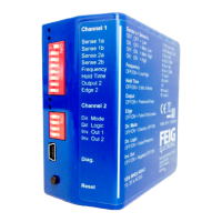
• Factory defaults can be found in the quick start guide and no the housing.
• The operating principle used (open circuit or closed circuit) is displayed in the Detector Tool .
Signal output according to the open circuit principle
Signal output according to the closed circuit
principle
Tab. 23: Inversion of output signal
11.7 Behaviour in the event of loop error (error mode)
The way a loop error is handled and what status the assigned output will take is selected in the Error Mode
setting.
Settings in the Detector Tool
The settings can only be changed in the Detector Tool.
as for occupied loops (factory setting)
if the Error checkbox is activated, loop errors for this channel will be transmitted.
The Error Mode field then shows as Active (factory setting).
if the Alignment checkbox is activated, the duration of the frequency adjustment of
the loop will be considered an error. This option is permanently switched off as the
default.
Tab. 24: Error mode settings
11.8 Assigning an output to a loop (Assignment)
A loop channel or a travel direction can be assigned to each output when direction detection is activated
(dual-channel variants only).
Settings in the Detector Tool
The settings can be changed in the Detector Tool.
 Loading...