VEK MNH Operating Manual v1.3 en
Direction A: Loop 1→Loop 2 or direction B: Loop 2→1
Signal output direction A or B
Direction logic system
• With all the logics, the first loop covered determines the direction of counting or of travel. If loop 1 is
covered first, the signal output and counting is done for direction A (see "0 Direction detection
principle", page 42).
• In the factory settings, travel direction A is output via hardware output 1, and travel direction B via
hardware output 2. The assignment of the signal outputs can be changed (see "11.8 Assigning an
output to a loop (Assignment)", page 40).
Counter readings in the Detector Tool
• The counter readings are displayed in the Detector Tool. It should be noted that the counter
overflows at 65,535 (2
16
) and is automatically erased.
• The counter readings are not protected against power failure!
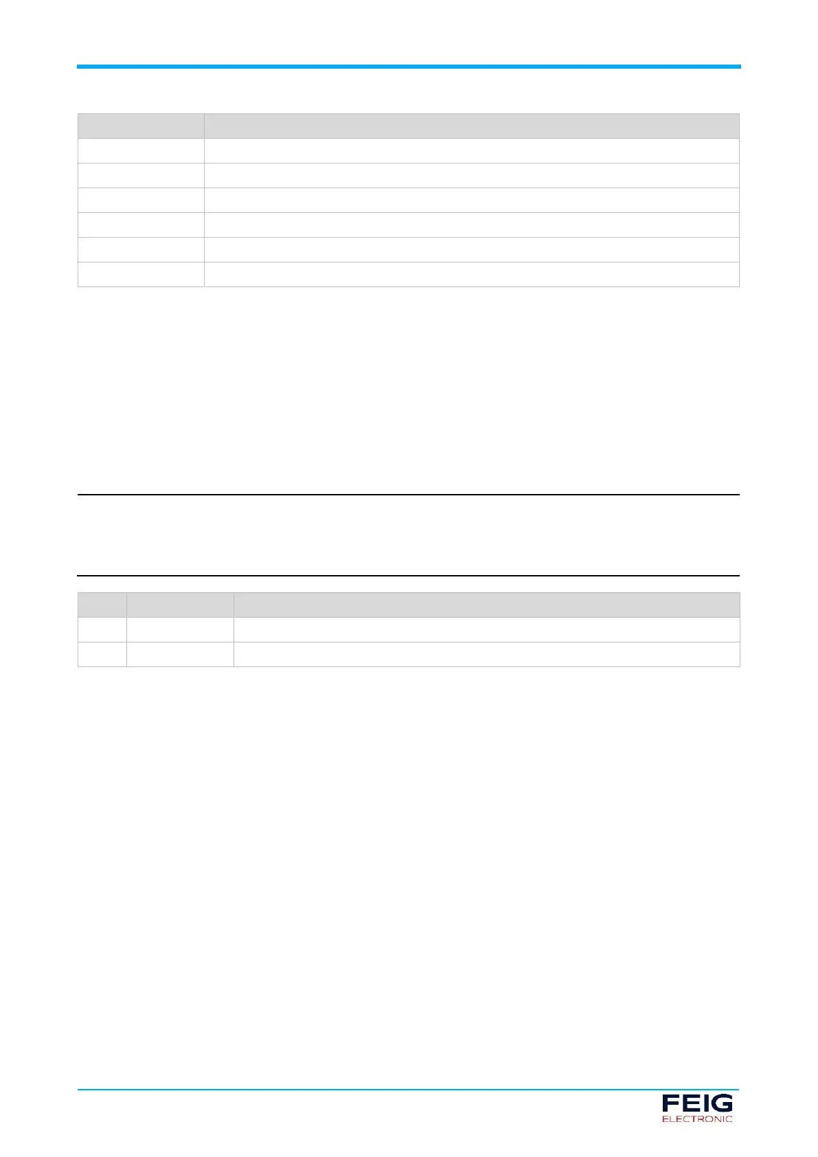
Switched off (factory settings)
Tab. 30: Setting direction detection
 Loading...