13 Remove all the bolts and washers joining the sump
casting to the crankcase making a special note of the
location of bolts of different lengths.
14 Mark the flywheel and crankshaft to ensure correct
reassembly and release the six flywheel retaining bolts
together with the lockwashers and lift away the fly-
wheel.
15 Using Fiat tool A.60156 on the two central studs, lock
the two cylinder barrels in place (see FIG 1 :11).
16 Turn the engine upside down ensuring that no weight
is placed on the studs.
17 Mark the connecting rods and end caps to ensure cor-
rect reassembly and remove the end caps. Place the
engine on its side and remove the cylinder barrels
clamp. Ensure that the studs are clean and carefully
slide off the connecting rod-piston-cylinder assem-
blies from the crankcase.
18 Remove the six screws holding the rear bearing hous-
ing to the crankcase and lift away the housing. Remove
the six screws holding the front main bearing housing
to the crankcase and lift away its housing.
19 Carefully ease the crankshaft from the crankcase
moving it diagonally to assist withdrawal.
20 To ensure no damage occurs to the long cylinder
barrel mounting studs these may be removed using
Fiat puller A.40010 or a universal stud remover as
shown in FIG 1 :12.
1 :6 Cylinder head removal, servicing and replace-
ment
Description:
The aluminium cylinder head is finned to increase the
cooling surface. Through bolts secure the head and the
two cylinders to the crankcase. The valves are controlled
by a camshaft through tappets, pushrods and rockers. The
connection between the head and the crankcase is via five
sleeves mounted directly between the head and crankcase,
and these accommodate the pushrods, lubricating oil and
passage for the crankcase gases. The cylinder head has
been
modified for the 110 F and later 120 engines as
they now incorporate a heater safety device as described
in Section 4:4.
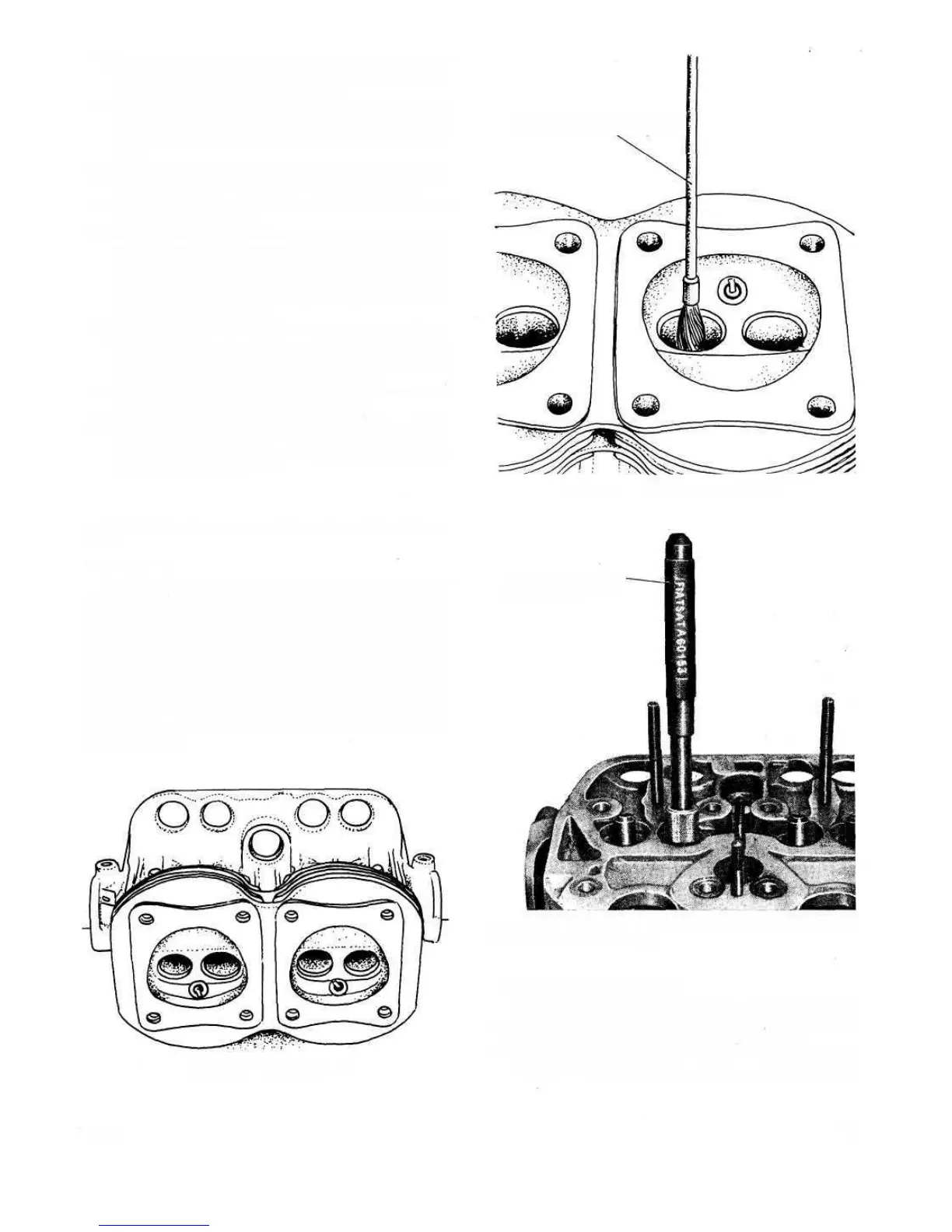
FIG 1:15 Cylinder head
17
F500
The cylinder head should be removed whenever the
valves require attention or the engine to be decarbonized.
To remove the cylinder head proceed as follows:
1 Remove the air cleaner, carburetter, rocker cover and the
screws securing the blower conveyor to the cylinder
Removal of cylinder head:
FIG 1 :17 Installing a valve guide using Tool A.60153
provided with pilot bush
TOOL A. 60153-
WITH PILOT BUSH
FIG 1:16 Cleaning valve guides
WIRE BRUSH A.11417 / BIS