Insert a .0079 ± .00197 inch thick oil paper gasket
between the crankcase and cylinder bottom face and a
.0236 to .0275 inch thick graphitized asbestos gasket
between the cylinder and cylinder head. The compression
of the gaskets on assembly will eliminate any very small
differences between the two mating surfaces.
Inspection of tappet seats:
The tappet seats should be checked for scoring and
correct clearance which must not exceed .00315 inch.
Should the clearance be greater than the maximum
specified the seating may be reamed to oversize dimen-
sions as detailed in Technical Data. Tappets are avail-
able in .00197 and .00394 inch diameter oversize.
1 :9 Piston assembly
Inspection:
Before inspection the pistons must be thoroughly
cleaned and the ring grooves and piston head decarbo-
nized. Check for deep score marks and signs of distortion
or fracture especially around the skirt and piston pin areas.
Using a feeler gauge ensure that the piston clearances in
the bore do not exceed a maximum of .0059 inch for the
Model 500 engine and .0079 inch for the Model 500
sports engine (see FIG 1 :25). The measurements should
be taken at the bottom of the skirt and square to the piston
pin axis.
Should the clearance be greater than the maximum
permissible, the cylinders may be rebored and oversize
pistons fitted to m
atch them. Pistons are supplied in the
following oversizes, .0079, .0157 and .0236 inch. It
should be noted that oversize pistons and rings are not
available for the Model 500 sports engine so if the piston
to cylinder wall clearance is greater than the permissible
maximum limit the cylinder and piston assembly must be
renewed.
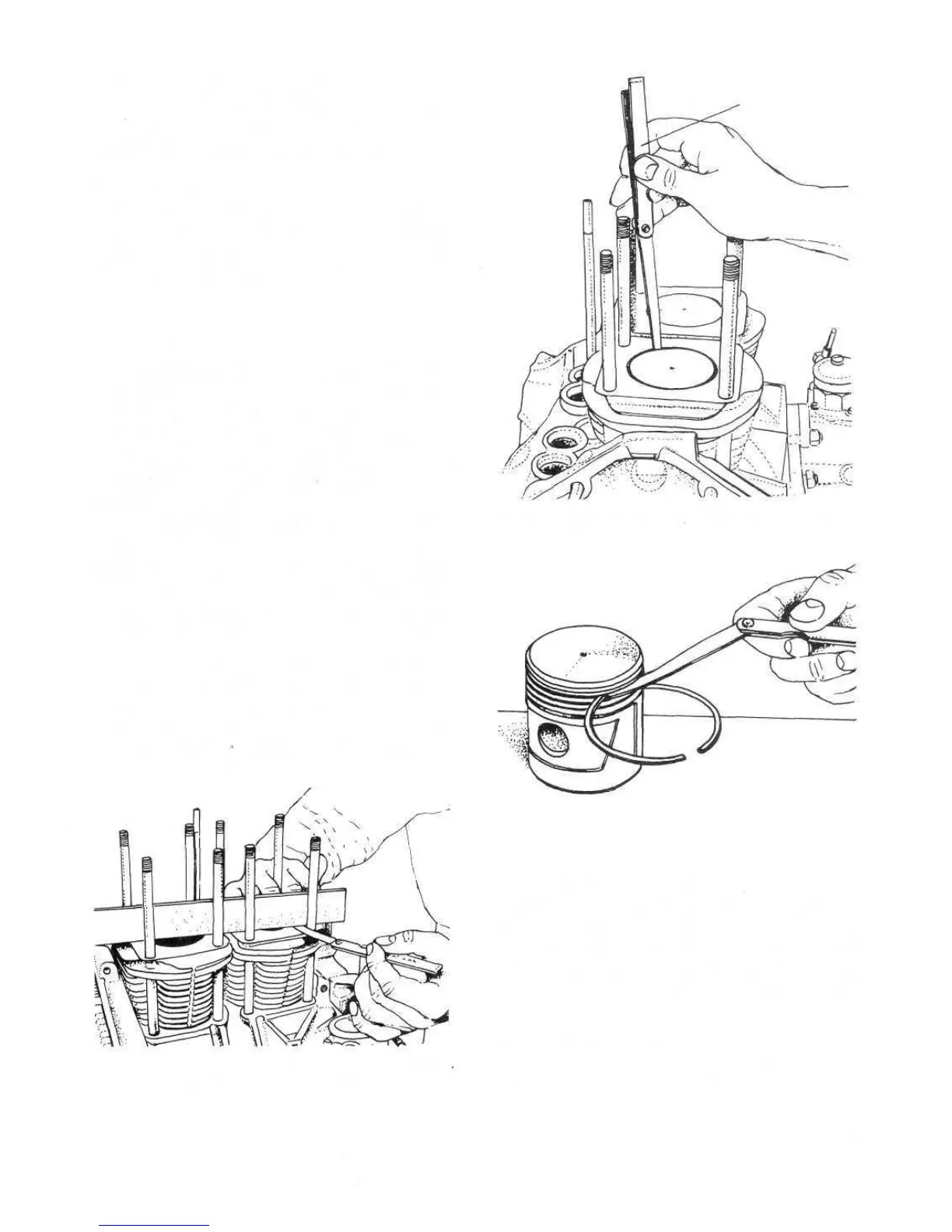
The piston ring to groove clearance must be checked as
shown in FIG 1 :26 and the ring gap when fitted as in
FIG 1 :27. In both cases the readings should be
compared with the piston data. Piston rings are available
in the same oversize classes as the pistons. When
installing piston rings the gap should be placed opposite to
the piston expansion stops. Ensure that the ring gaps are
scattered and not in a line.
FIG 1:24 Checking cylinder head mating face for level
Out-of-true should not exceed .00315 inch
F500
21
The installation of the piston and connecting rod should
be carried out on a clean workbench as shown in
Reassembly of piston:
Check that the fit between the piston pin and boss is a
pinch fit. If excessive clearance is found the boss may be
reamed and a .0079 inch diameter oversize piston pin
fitted. The pin to bore pinch fit must be between .0000 to
.0039 inch. At all times the pins should be installed only
after the piston has been heated in hot water to a tempe-
rature of 80°C. Upon reassembly of the piston to the
engine the expansion slot must be placed facing the cam-
shaft.
FIG 1 :26 Checking piston ring-to-land clearance
FEELER GAUGE C.316
FIG 1:25 Using feeler gauge C.316 to check piston-to-
cylinder wall clearance