of wear, distorting or unevenness of the surfaces as this
part is very heavily pressed when the vehicle is negotia-
ting a corner. If the clearance to the idle pinions exceeds
.0059 inch the shaft must be renewed.
2 Inspect the ring gear and pinion seat, the side gears.and
the idle pinions for correct meshing. This will be shown
up by white marks on the sides of the gear teeth. Check
that none of the teeth are broken, chipped or exces-
sively worn and if any part is suspect then it must be
renewed not forgetting that the ring gear and pinion
come as a matched pair.
3 Inspect the condition of the ball and roller bearings, the
rollers and balls and working faces must not show signs
of pitting wear or cracking and if any part is suspect then
the race must be renewed.
4 Check that there is not any undue wear on the faces of
the thrust rings. Any slight indentations may be evened
out using a fine oil stone but if the damage is excessive
then new rings or oversize rings must befitted as neces-
sary. Thrust rings are supplied as service spares in the
following thicknesses.
Standard .0394 inch
Oversize .0512-.0591 inch
6:6 Reassembly—differential unit
To reassemble the differential case proceed as follows:
1 Press onto the differential half housing which carries
the ring gear one differential bearing inner race ensuring
that it is pushed fully home onto its seating. Install the
thrust ring and side gear (see FIG 6 :7).
2 From the inside of the case insert the axle shaft com-
plete with pivot and runners that form the slip joint.
Also install the idle pinions and carrier shaft. Position
the ring gear onto the housing half and install the
differential pinion shaft retainer ring.
3 Press the other differential bearing inner race onto its
seating on the left differential housing half and replace
the left axle shaft complete with slip joint.
4 Join the two case halves together and tighten the
retaining screws and also the retaining screws of the
ring gear to a torque wrench setting of 23.1 Ib ft. Secure
all screws by bending up the lockplates.
5 Press the differential bearing outer races into their
seatings in the bearing housings and also fit the oil seals.
Also install the bearing housings over the driving shafts
together with the adjuster rings.
6 Install the differential unit assembly into the final drive
housing front half and bolt the rear
half onto it. Tighten
the six mounting nuts to a torque wrench setting of
27.5 Ib ft. Finally place the bearing housings in their
seats and tighten the mounting nuts to a torque wrench
setting of 13 lb ft.
It should be noted that after the gearbox has been over-
hauled the complete differential unit should only be in-
stalled after the drive pinion depth adjustments has been
carried out.
6:7 Final drive gear set adjustment
The installation and adjustment of the final drive gear
set requires special care otherwise the unit may have to be
dismantled again for further adjustment. So as to establish
the correct mesh of the two gears, their relative position is
accurately set during initial assembly at the factory.
F500
71
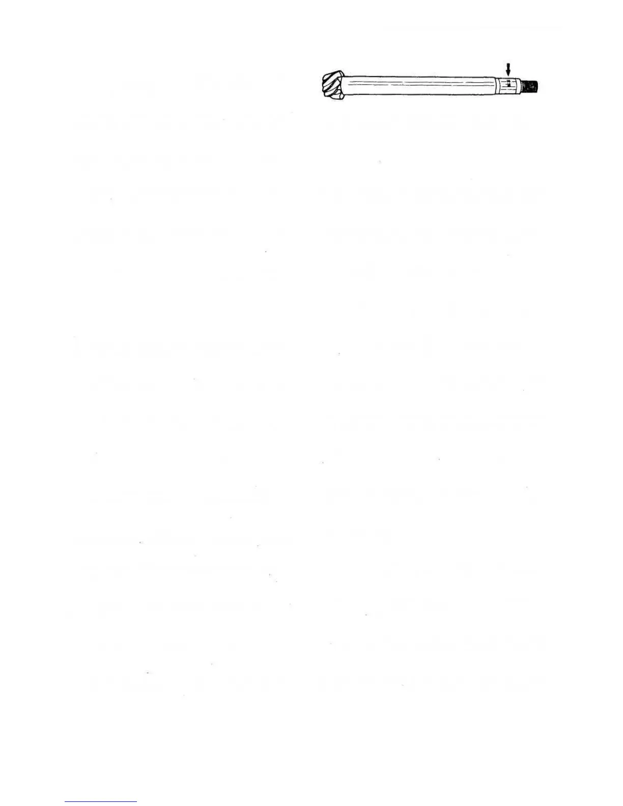
Refer to FIG 6 :8 where it will be seen that two numbers
are stamped on the pinion shaft near to the threaded end,
the upper number is the matching number which should
also appear on the crownwheel. The lower number indi-
cates the positive or negative deviation from the theoretical
distance between the centre line of the ring gear and the
pinion face. It is this number which must be taken into
account when calculating the adjusting shim thickness
which has to be fitted between the rear roller bearing and
the fourth-speed gear on the layshaft.
The formula from which the adjusting shim thickness
can be calculated is as follows:
S=A—(B + C)
Where S=shim thickness.
A= distance between the front bearing inner
race and the centre line of the ring gear.
B = distance of the drive pinion face to the ring
gear centre line.
C=the total of the widths of the third-speed
gear bush, third- and fourth-speed hub,
fourth-speed gear bush and rear roller
bearing inner race fitted onto the mainshaft
It should be noted that 'A' is the total of half the diameter
of the differential bearing housing seat which is in actual
fact 41.00 mm, and the distance measured between the
front bearing inner race and the differential bearing housing
seat. The last
dimension will have a minimum manufactu-
ring limit of 150.54 mm. Any deviation from this value
must be determined and considered when determining
the total shim thickness 'S'.
A= 150.54 + 41.00 + a (deviation)
To determine deviation 'a' Fiat tool A.62036 should be
assembled to the gearbox casing as shown in FIG 6:9
and to take the reading proceed as follows:
1 Assemble the front ballbearing and its retainer into the
gearbox housing and tighten the retainer bolts.
2 Hold the gearbox housing in the vertical position with
the differential side upwards and insert Fiat tool
A.62036 carefully from above into the bearing bore and
lock it firmly by tightening the knurled nut.
3 Using Fiat dial gauge C.689 which has been previously
zeroed on a surface plate should next be mounted
onto the top of Fiat tool A.62036 with its pointer resting
on the lowest position of the differential bearing hous-
ing bore as shown in FIG 6:10. To obtain the lowest
point move the pointer to both sides of the bottom dead
centre position so as to obtain the maximum reading.
The distance 'B' in the formula for calculating the shim
thickness is designed to have a lower manufacturing limit
of 75 mm. Any deviation 'b' is stamped on the drive pinion.
Therefore to calculate the value of 'B'
B= 75+ b (deviation)
The distance 'C' in the formula for calculating the shim
thickness is designed to have a lower manufacturing limit
FIG 6:8 Layshaft with final drive pinion. The arrow
points to the number (14) for correct mating with ring
gear and to the centesimal figure (—10) for accurate
mating position of pinion and gear