FIG 1 :40 Engine detail showing lube oil passages
Key to Fig 1 :40 1 Splines in crankshaft for oil passage
to filter 2 Oil inlet into circuit from filter 3 Hole for
oil passage to main bearing
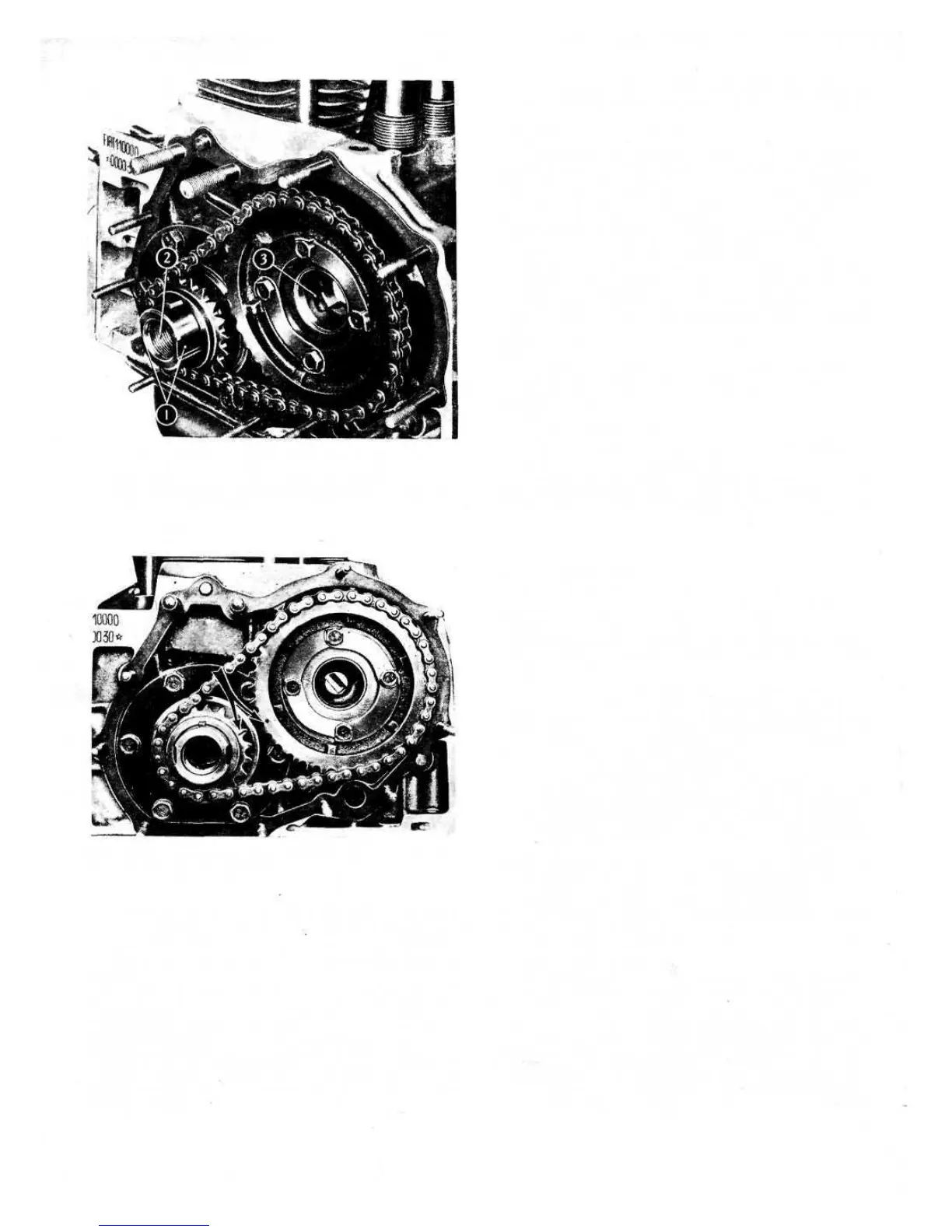
FIG 1 :41 Timing marks on sprockets. On later cars the
crankshaft key way is on the underside
size that centrifugal force does not sling oil into the area
where the foreign matter is collected. The outer flange
inner face has radial vanes on its face which retain the
foreign matter and the oil is conveyed to the centre of
the filter.
The oil to be filtered issues from the side splines 1
(see FIG 1 :40) of the crankshaft and is forced by the
slinger to the periphery of the filter where it is cleaned and
returns to the centre of the filter and into the crankshaft
drilling 2. The inner flange or hub and the slinger are
secured to the crankshaft by a special hollow screw 6 as
shown in FIG 1 :39, the outer flange is attached to the
hub by six screws.
28
If the camshaft has been disconnected from the crank-
shaft for any service operation the valve gear will have to
be retimed and to do this proceed as follows:
1 Turn the crankshaft until the reference line on its
sprocket is pointing towards the camshaft as shown in
FIG
1
:41.
2 Turn the camshaft until the reference dot on its
sprocket registers with the crankshaft sprocket. Leave
the shafts undisturbed and carefully mount the chain.
Should it be necessary to check the valve timing and
sprocket marks, proceed as follows:
1 Fit Fiat C.673 tool as shown in FIG 1 :42.
2 Temporarily adjust the valve stem-to-rocker arm
clearance of cylinder No. 1 at .01 77 inch for the inlet
valve and .01 50 inch for the exhaust valve (Model 500
engine) or at .01 54 inch for both valves (Model 500
sports).
3 Rotate the crankshaft and set the flywheel timing mark
at 'O' on the graduated sector. Check that the sprocket
marks are correctly lined up in this position.
If the engine is being assembled, to install the driven
gear, proceed as follows:
1 Set the timing mark on the drive sprocket towards the
centre of the camshaft.
2 Position the driven sprocket on the camshaft mounting
flange with four screw holes in line and tighten two
mounting screws only.
3 Rotate the camshaft until the driven sprocket mark
registers with the reference line on the drive sprocket.
4 Remove the driven sprocket without moving the
camshaft. Install the timing chain and replace the
driven sprocket. Tighten the four screws to a torque
wrench setting of 6.5 Ib ft.
1:15 Valve timing
The oil pressure indicator sender unit is located on the
righthand side of the cylinder block and is connected to
an indicator light in the instrument cluster on the dash-
board.
The red indicator lights only when the ignition is
switched on and goes out when oil pressure has built
up to between 8.5 and 14 Ib/sq in.
Should an accidental shortcircuit occur in the oil
pressure indicator circuit, the sender unit may be damaged
so the cause must be traced and rectified before the unit
is renewed.
Oil pressure indicator sender unit:
To ensure a reliable lubrication system there must be
no oil leaks from the gasket between the outer and inner
flanges. Every time the engine is overhauled the filter
must be dismantled, cleaned and new gaskets fitted.
To clean the filter, remove the six screws and washers
and separate the drive pulley and hub. Carefully scrape
the inner surfaces to remove all sludge.
Upon reassembly the filter to crankshaft hollow
mounting screws must be tightened to a torque wrench
setting of 1 08.5 Ib ft. The cover to mounting flange screws
must be tightened to a torque wrench setting of 5.8 Ibft.
Cleaning and inspection:
A groove is machined on the outer flange periphery to
form a pulley for the generator and blower drive belt.