FEELER GAUGE
Checking ring gap (ring in cylinder)FIG 1 :27
FIG 1 :28.
A universal piston ring compressor should be
used to keep the rings tight in their grooves. The correct
matching of the piston and connecting rod is described in
a later section of this chapter.
1 :10 Connecting rods
Checking rod bearing inserts and crankpin jour-
nals:
The big-end bearing halves are of the babbit lined thin
wall type and must not be modified in any way. Should
score marks or excessive wear be evident the bearing
inserts must be renewed. It is recommended that if the
bearing inserts are to be renewed due to wear the crank-
pins should be measured to see if regrinding is required.
Before regrinding the crankpins they should be
measured at the maximum point of wear to determine the
class of bearing undersize to be fitted after regrinding the
crankpins. Undersize bearing halves are available in the
following sizes .01, .02, .03 and .04 inch. The correct
bearing crankpin clearance is .00043 to .00240 inch and
must be checked as detailed in the following section.
Checking rod bearing insert to crankpin journal
clearance:
Before the crankshaft is installed into the engine after
overhaul the clearance must be checked to ensure that it is
within the manufacturers recommended limits. To check
the clearance proceed as follows:
1
2
Lubricate the crankpin and bearing inserts and install
the connecting rod together with its bearing halves on
the crankpin. Tighten the cap nuts to a torque wrench
setting of 23.9 Ibft.
Rotate the connecting rod around the crankshaft jour-
nal several times to seat the bearing insert correctly.
Remove the bearing end cap and carefully wipe away
all traces of the lubricant.
22
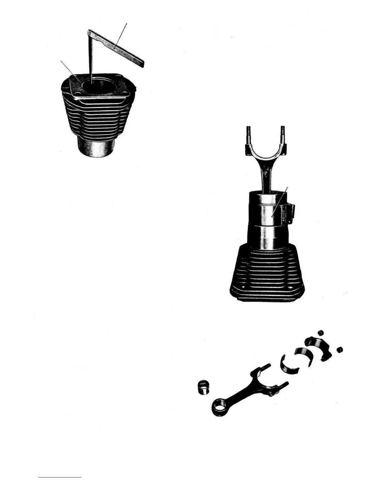
FIG 1 :29 Connecting rod components
Piston installer A.60154
FIG 1 :28
PISTON INSTALLER
A. 60154
If the clearance indicated is within the recommended
FIG 1 :31.
4
Place a piece of 'Plastigage type PG-1' along the full
width of the bearing insert along the crankshaft
longitudinal axis (see FIG 1 :30). Refit the bearing cap
and tighten the nuts to a torque wrench setting of
23.9 Ib ft. Remove the bearing cap and upon inspection
the 'Plastigage' will be found to have adhered to either
the crankpin or bearing insert and will have developed a
rectangular section. To determine the actual clearance
between the crankpin and bearing insert compare the
width of the flattened 'Plastigage' at its widest point
with the graduations on the envelope as shown in
3
PISTON RING