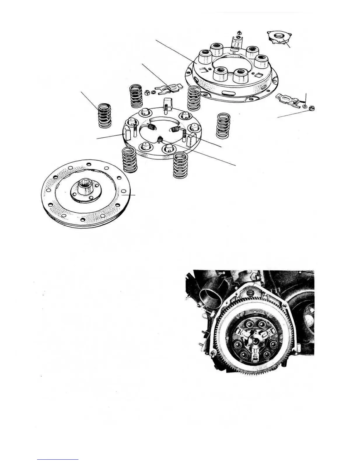
FIG 5:2 Clutch components (new 500, 500D sedan and early station wagon)
DRIVEN PLATE
PRESSURE PLATE
LEVER CARRIER
LEVER BOLTS
BOLT NUTS
PRESSURE SPRINGS
WITHDRAWAL LEVERS
CLUTCH COVER
LEVER CARRIER RING
SPRING
WASHER
FIG 5:3 Clutch assembly installed on engine (new
500, 500D sedan and early station wagon)
61
F500
To check the correct operation of the clutch cover
500 sedan (110.F) late 500 station wagon :
Inspection—diaphragm clutch:
5 Finally tighten down the cover assembly using the three
T-handles and adjust the clearance between the carrier
ring and its central shoulder by means of the three
adjustment nuts.setting the withdrawal levers stroke to
0039 inch. Check this adjustment using Fiat gauge
C.110 and when correct lock the adjustment nuts by
peining to the lever bolts.
500D sedan and early station wagon:
To assemble the clutch cover assembly proceed as
described above but adjust the withdrawal levers as
follows:
1 Secure the clutch cover assembly to Fiat fixture A.62038
with a ring .5413 to .5433 inch thick placed between
the clutch cover plate and the pressure plate.
2 Adjust the height of the three withdrawal levers so that
the lever tips are 1.9094 inch from the face of the Fiat
supporting plate.