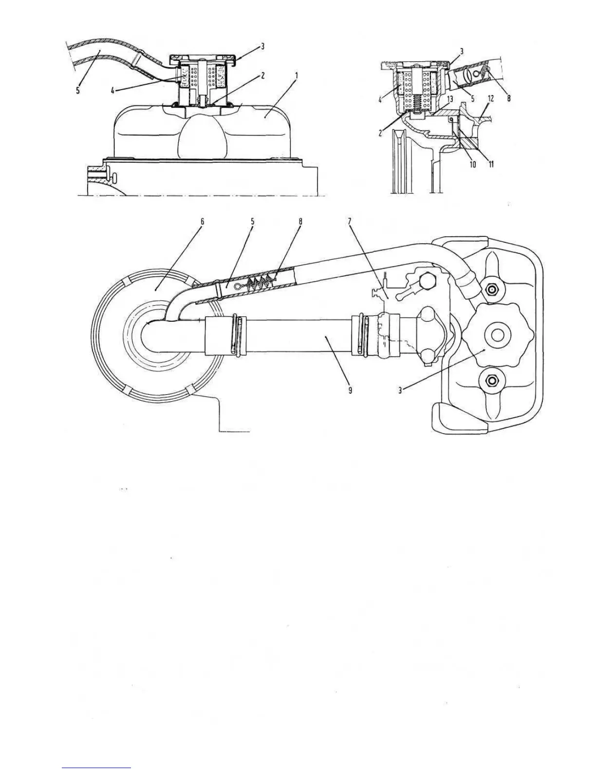
FIG 2:18 Diagram of blow-by gases re-circulation device
Key
to
Fig
2:18
1 Head cover 2 Blow-by gases and oil vapours breather valve 3 Oil filler cap
4 Strainer
9 Air suction pipe, air cleaner to carburetter
8 Flame trap
13 Exhaust duct
12 Crankcase
7 Carburetter6 Air cleaner
11 Filter gauze
10 Movable partition
5 Pipe
Engine 110 F. 000 Engine 120.000
designed to dampen the air intake noise and the carburet-
ter venturi hiss and is so located in the blower conveyor
system so that only clean dry air is drawn into the induc-
tion system.
To ensure complete protection of the engine it is
recommended that the air filter element be replaced every
6000 miles or even earlier if the vehicle is operating in
dusty conditions.
It should be noted that an oversize air cleaner may be
obtained if the vehicle is to be operated in very dusty areas.
Air cleaner—engine 110 F.000:
To remove the air cleaner element, disengage both the
spring hooks 2 as shown in FIG 2:17 and lift away the
cover 4 by turning it inwards together with the hose 5.
2:9 Air cleaner (sedan)
The pleated paper air cleaner element is contained in a
casing housed in a recess of one of the silencing chambers
provided in the blower conveyor as shown in FIG 2:16.
The air cleaner is connected to the carburetter by means of
a specially shaped hose. The silencing chamber is
44
For full instruction refer to Section 2 :6.
Carburetter cleaning:
See Section 2 :6 for full check details.
Throttle valve components:
Engine 110 F. 000