Drain the oil sump to ensure that the oil does not syphon
out. Thoroughly clean the area around the pump body
(see FIG 1 :37).
Remove the end cover plate by releasing the retaining
bolts and washers. Carefully ease the driven gear down-
wards followed by the driving gear and shaft
Clean all parts removed and blow clean using a com-
pressed air jet. Inspect the timing gear cover pump area
for cracks or distortion. Check that the inner duct for oil
delivery to the pump is clear of obstruction. If in doubt
remove the drain plug and filler cap and use a com-
pressed air jet to clean the passage.
Check the gear teeth for damage or excessive wear,
ensure that the drive gear is firmly attached to its spindle
and that the end cover plate is not badly scored or pitted.
Fit new parts as necessary.
Reassembly is the reverse procedure to dismantling,
taking care that all parts are assembled clean and the
end cover plate seating correctly with a new gasket.
5
4
3
2
1
1:14 Lubrication, oil filter, relief valve
Description :
The engine is pressure lubricated through a gear type
pump which is incorporated in the timing gear cover and
driven from the camshaft by dogs or gears. The lubrication
circuits are shown in FIGS 1 :36 and 1 : 37.
The pump draws oil from the sump through a suction
horn fitted with a filter screen which is fixed to the crank-
case by a duct in the timing gear cover. This
supplies oil
to the pump.
Oil passes from the camshaft rear seat onto the crank-
shaft rear support where it flows into an adjacent chamber.
From here the oil flows through ducts in the crankshaft
from end to the centrifugal oil filter. The centrifugal filter,
which also acts as a pulley for the generator and blower
drive, rotates with the crankshaft.
Oil from the filter enters a passage in the crankshaft,
where it lubricates the main and connecting rod bearings
and passes from a special groove in the front main
bearing and ducting in the crankcase into which is
inserted the oil pressure warning sender unit, and also
the delivery pipe for oil to the overhead valve gear.
The pushrod sleeves provide the return path for the oil
from the cylinder head and delivers oil to the tappet gear
and the camshaft cams. The tappets are suitably drilled
to allow correct circulation of the oil. The tappets are
located in two casting cavities, one of which com-
municates with the timing gear housing and the other
one to the crankshaft front drain support drain.
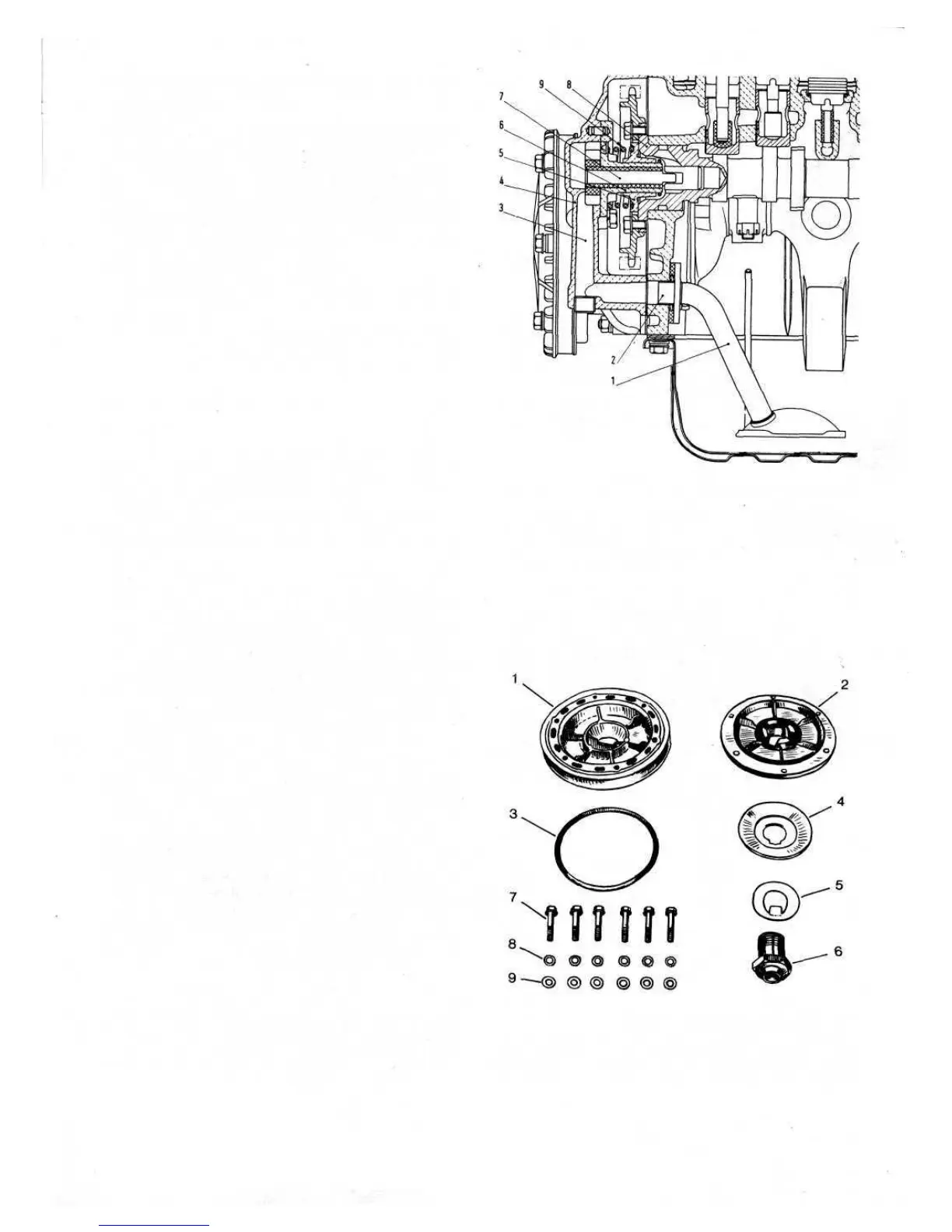
The oil pressure is regulated by a pressure relief valve 5
(see FIG 1 :38) mounted at the rear end of the camshaft.
It comprises a hubbed disc which slides on a guide 6 of
the oil pump drive shaft 7. Under spring load 9 the valve
disc circumferentially closes an annular chamber which
communicates with the lubrication circuit. Excessive oil
pressure causes the disc to uncover the chamber.
Centrifugal oil filter:
The oil filter is of the centrifugal type comprising of
two flanges and an oil slinger. The filter is attached to the
rear end of the crankshaft as shown in FIG 1 :38. The
outside diameter of the oil slinger (see FIG 1 :39) is
smaller in diameter than that of the flanges but of such a
F500
27
Key to Fig 1:39 1 Drive pulley 2 Rotor hub
3 Seal ring 4 Oil slinger 5 Lockplate
6 Hub-to-crankshaft hollow screw 7, 8, 9 Pulley-to-hub
mounting screws, toothed washers and plain washers
FIG 1:39 Centrifugal oil filter components
Key to Fig 1 :38 Suction scoop 2 Hole in crankcase
3 Duct in timing sprocket cover 4 Timing sprocket cover
5 Oil pressure relief valve 6 Drive shaft guide and oil
pump cover 7 Oil pump driving gear shaft 8 Camshaft
9 Oil pressure relief valve spring
FIG 1:38 Engine longitudinal section through oil pump