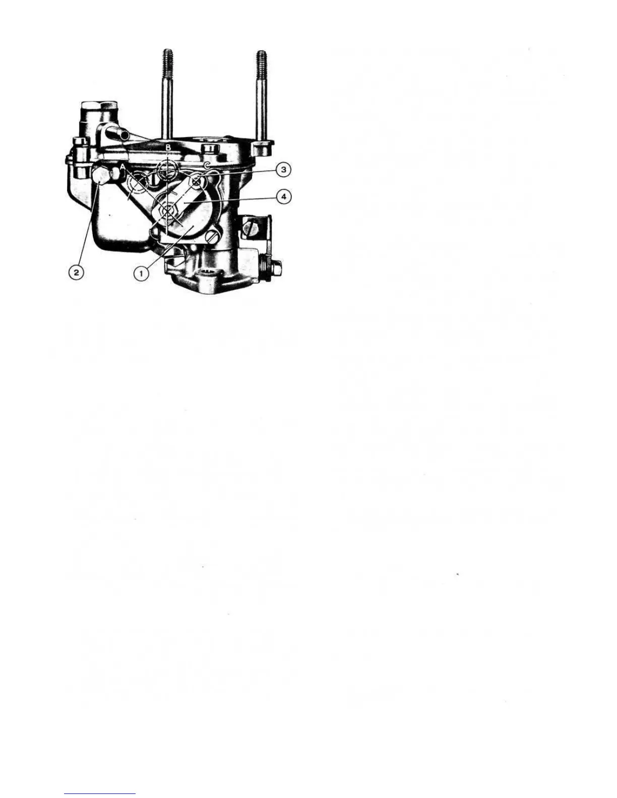
FIG 2:6 Weber 26.IMB carburetter starting device
(choke) end
Key to Fig 2:6 1 Choke device cover 2 Bowden
mounting screw 3 Nut and screw, choke bowden wire
4 Choke control lever A Position of lever 4 for 'fully
inserted' choke B 'Partially inserted' choke
C 'Disinserted' choke
caused by the engine suction and the charge is then drawn
into the cylinders.
The secondary venturi 24 is to increase the vacuum
around the nozzle 25 and to carry the charge to the centre
of the primary venturi 21.
When the engine is idling, fuel is carried from the well
23 via an appropriate passage to the idle speed jet 13
where it is mixed with the air coming from the air inlet 5.
Through duct 3 and idle speed orifice 18 (adjustable by
means of a taper point screw 17), the fuel reaches the
carburetter throat, past throttle butterfly 19 where it is
further mixed with the air stream drawn in by the engine
vacuum through the gap around the throttle in the idling
speed position.
From the duct 3 the mixture can also reach the car-
buretter throttle chamber through a transition hole 20
which is located in exact relation to the throttle butterfly.
The purpose of this progression hole is to permit a smooth
acceleration of the engine from the idling speed, this being
proportional to the increase in the throttle opening.
Starting device:
This enables the engine to be started when it is cold
under the most arduous of weather conditions. It is con-
trolled by means of a lever placed behind the gearshift
lever and must be progressively adjusted to its normal
rest
position as the engine reaches the normal operating tem-
perature. The starting device comprises a valve 33 (see
FIG 2:5) actuated by the lug of the rocker 36 which is
connected to the control lever 38 by a suitable shaft. By
38
pulling the device control fully across through lever 38
and rocker 36, the valve 33 is lifted from its seating and
brought into the 'fully open' position. Refer to diagram 'A'
(FIG 2:5). Under these conditions the valve 33 closes
the air hole 27 and the mixture hole 29 and uncovers
mixture orifices 30 and 32 which also communicate with
the starting jet 46 through a duct 26 and air holes 35.
With the valve 33 partially open the hole 29 may com-
municate with the carburetter throat through the valve
central slot, duct 28 and the hole 31 drilled in the venturi
21 corresponding with the venturi restriction.
When the throttle is set at the idling speed position, the
engine vacuum caused by the operation of the starter
enables the fuel contained in the recess of jet 46, in the jet
and in the reserve well 45 to be mixed with the air coming
from holes 43 and 44. The mixture arrives through the duct
26 and holes 30 and 32, at the same time as air passing
from the holes 35, past the throttle through duct 34 so
permitting easy starting of the engine.
After the engine has fired initially, the device will deliver
a charge with a rich petrol/air ratio so as to permit regular
running of the engine whilst it is cold. As soon as the
engine has warmed up to normal operating temperature
this charge would obviously be too rich and therefore it is
necessary to gradually ease off the operation of the starting
device as the engine reaches its normal operating tempera-
ture. During this adjustment the valve 43 slowly uncovers
the hole 27 which will permit a greater amount of air to
enter through the spring guide hole 42 so weakening the
mixture at the same time as closing the progression holes
30 and 32 and air holes 35 the amount of mixture is also
reduced. See diagram 'B' (FIG 2:5).
The hole 29, the duct 28 and the hole 31, which are
drilled in the venturi 21 permit a regular progression of
acceleration whilst the engine is cold as well as when it is
at normal operating temperature. By opening the throttle
butterfly 19 to increase the speed of the engine the
vacuum acting on the duct 34 is decreased. This causes a
drop in the amount of fuel delivered through duct 34 with
consequent irregular running of the engine but, through
hole 31, duct 28 and hole 29 some charge is sucked in by
the vacuum formed in the restriction of the venturi, caused
by the opening of the throttle and this automatically com-
pensates for the reduction in the delivery through the duct
34.
When the starting device is not in operation, valve 33
covers the hole 29 and so preventing the passing of fresh
charge. Diagram 'C (FIG 2:5).
Engine starting:
So that full advantage may be taken of the progressive
action starting device the engine should be started as
follows:
1 Cold starts:
The starting device should be moved across the position
'A', (FIG 2:6). Once the engine has fired push the control
in partially.
2 Warm starts:
Only partially move the starting device as shown in
position 'B' (FIG 2:6).