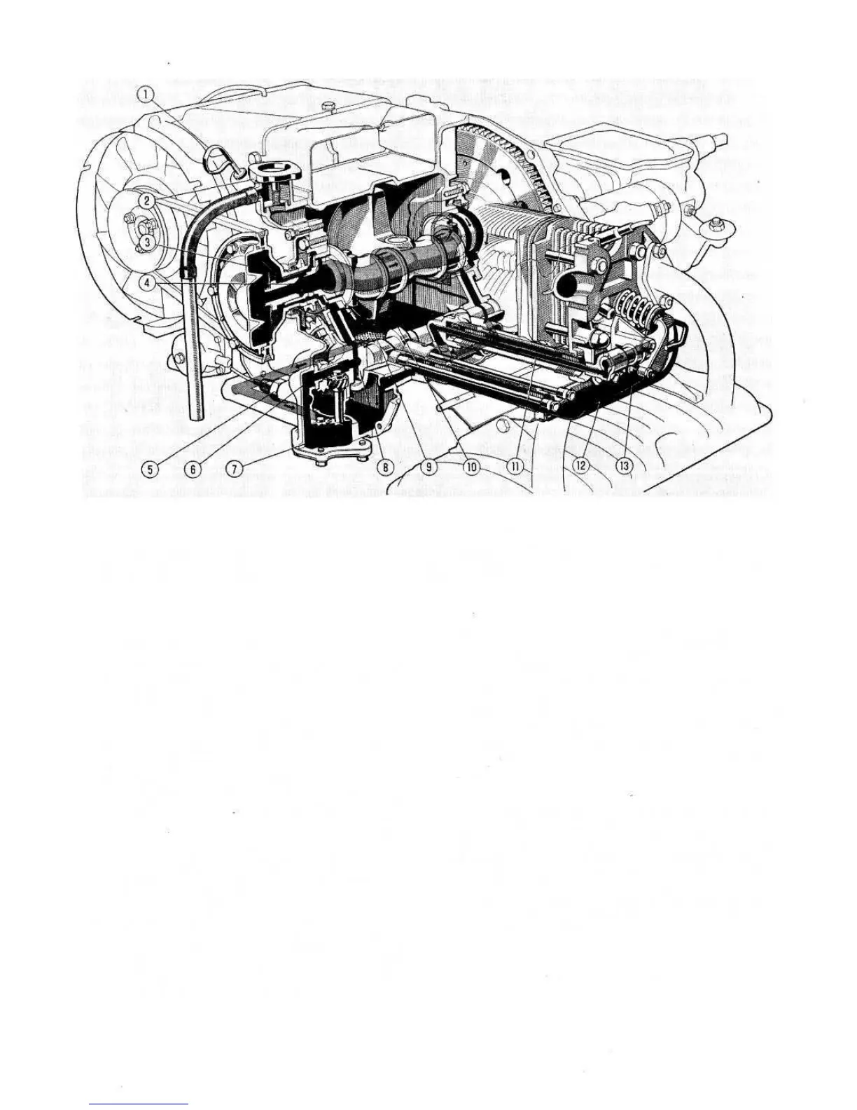
FIG 1:37 Lubrication diagram of engine 120.000
Key to Fig 1:37 1 Oil dipstick 2 Oil filler with vent valve 3 Centrifugal oil filter
4 Crankshaft, with central oil gallery 5 Low oil pressure indicator sending unit 6 Oil pressure relief valve 7 Gear pump
8 Camshaft, with central oil gallery 9 Oil suction filter from sump 10 Oil sump drain plug
11 Oil delivery line to rocker shaft 12 Rocker shaft 13 Head cover
Pump dismantling, inspection and reassembly:
Remove the lock ring and withdraw the pressure relief
valve and spring. Remove the oil pump cover plate and
ease out the gears and shaft.
Thoroughly clean all the parts and blow clean using a
compressed air jet. Inspect the timing gear cover for
cracks or distortion. Check that the inner duct for oil
delivery to the pump is clear of obstruction. Use a
compressed air jet to clean the passage.
Check the oil pump gear teeth for damage or excessive
wear and fit new gears if necessary. The recommended
backlash is .0059 inch with a maximum wear limit
giving a backlash of .0079 inch. Check the clearance
between the gear teeth and the housing walls in the
timing gear cover. The recommended clearance is .0012
to .0035 inch with a maximum of .0047 inch. Ensure
that the drive gear is firmly attached to its shaft. Upon
assembly there is a pinch fit of .0016 to .0031 inch
between the two parts.
The driven gear to shaft clearance upon assembly is
.00079 to .00236 inch with a maximum wear limit of
.0039 inch. Also check the width of the drive and driven
gears which when new should be .3937 to .3928 inch
with a minimum width of .3917. In service a spare drive
gear is supplied complete with its shaft.
26
4
3
2
1
Station wagon:
A helical-spur gear type oil pump is driven from the
lower end of the distributor drive spindle which is in mesh
with the camshaft. The gears are located in a special
housing in the bottom of the timing gear housing and are
held in place by a cover plate. The oil pressure relief valve
is located at the driven end of the camshaft.
A pump suction oil filter is fitted in the sump and this
connects to a duct in the timing gear case so supplying oil
to the pump (see FIG 1 :37).
Pump gears removal, inspection and reassembly:
To remove the pump gears from the timing gear cover
proceed as follows:
Inspect the filter screen on the end of the pump suction
scoop and remove any obstruction. If the screen is
damaged it must be renewed.
Check that the pump drive dog is a good fit on the cam-
shaft and that the dogs are not badly worn so as to
impair the pump operation.
Reassembly of the pump is the reverse procedure to
dismantling. Ensure that the pump cover piate is
correctly located by means of the dowel on the timing
gear cover.
5
6
7