39
38
28 29 30
A
31
32 33
28 29 30 3.1
B
28
29 30 31
C
34
34
34
37363523
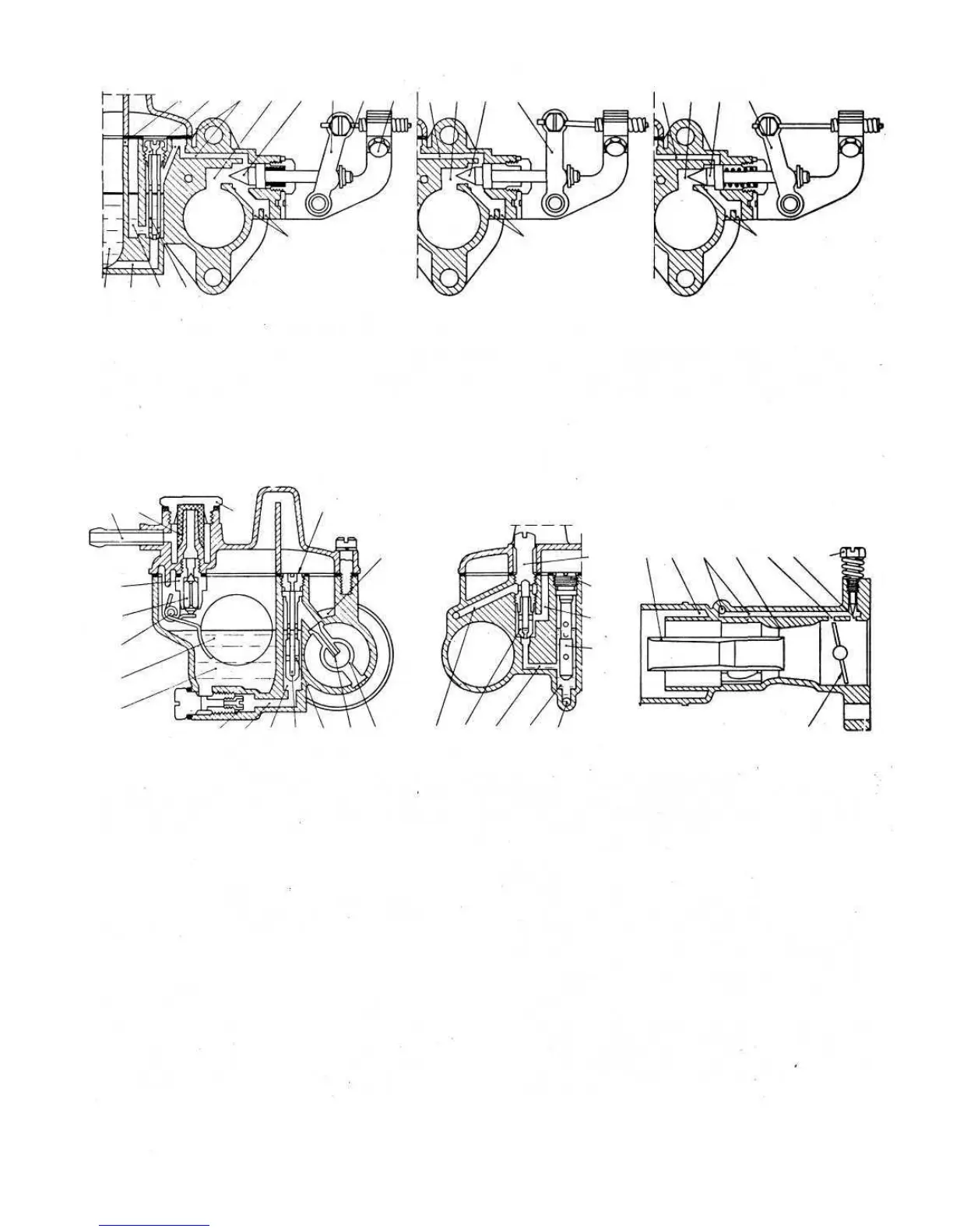
FIG 2:13 Diagrammatic section views of 26.OC Weber carburetter through the starting device
1
2
.3
4
5
27
26.
25,
24.
23.
22
16
17
8
21
20
9
_6
.4
7
.8
10 19 18
17
16 1 5
95
10
11
12
13
14.
FIG 2 :14 Diagrammatic section views of 26.OC Weber carburetter
Key to Fig 2:14 1 Fuel inlet connection 2 Filter gauze 3 Filter inspection plug 4 Air corrector jet
5 Air intake 6 Idle speed jet holder 7 Idle airduct 8 Emulsion tube 9 Secondary venturi 10 Idle mixture duct
11 Primary venturi 12 Progression hole 13 Idle orifice to duct 14 Idle mixture adjustment screw 15 Throttle
16 Bowl-to-well duct 17 Emulsion tube housing well 18 Well-to-idle jet duct 19 Idle speed jet 20 Nozzle
21 Emulsion orifices 22 Main jet 23 Bowl 24 Float 25 Float pivot 26 Valve needle 27 Needle valve
When the starting device is not in operation valve 30
covers the hole 29 so preventing the passage of mixture as
shown in diagram 'C (FIG 2:13).
Engine starting:
So that full advantage may be taken of the progressive
action starting device the engine should be started as
follows:
1 Cold starts. The starting device should be moved
across to position 'A' as shown in FIG 2:13. Once the
engine has fired push the control in partially.
42
2 Warm starts. Only partially move the starting device
to position 'B' as shown in FIG 2:13.
3 Engine warm-up. As the engine begins to warm up to
its normal operating temperature. Gradually push home
the starting device lever so as only to supply the engine
with the richened charge enabling the cold engine.
operation to be smooth and regular. Position 'B'shown
in FIG 2:13.
4 Normal car driving. Once the engine has reached its
normal operating temperature the starting device
should be completely brought out of operation by
bringing the control lever to the position C shown in
FIG 2:13.
Key to Fig 2:13
23 Bowl 28 Starting mixture duct
29 Starting mixture duct
30 Starting valve
34 Emulsion air orifices
38 Starting air corrector screw
C Choke disengaged
B Choke partially inserted
37 Starting jet
33 Bowden fixing screw
A Choke fully inserted
36 Starting reserve well
32 Starting device control wire
31 Starting device control lever
35 Bowl-to-starting jet duct
39 Reserve well emulsion air slot