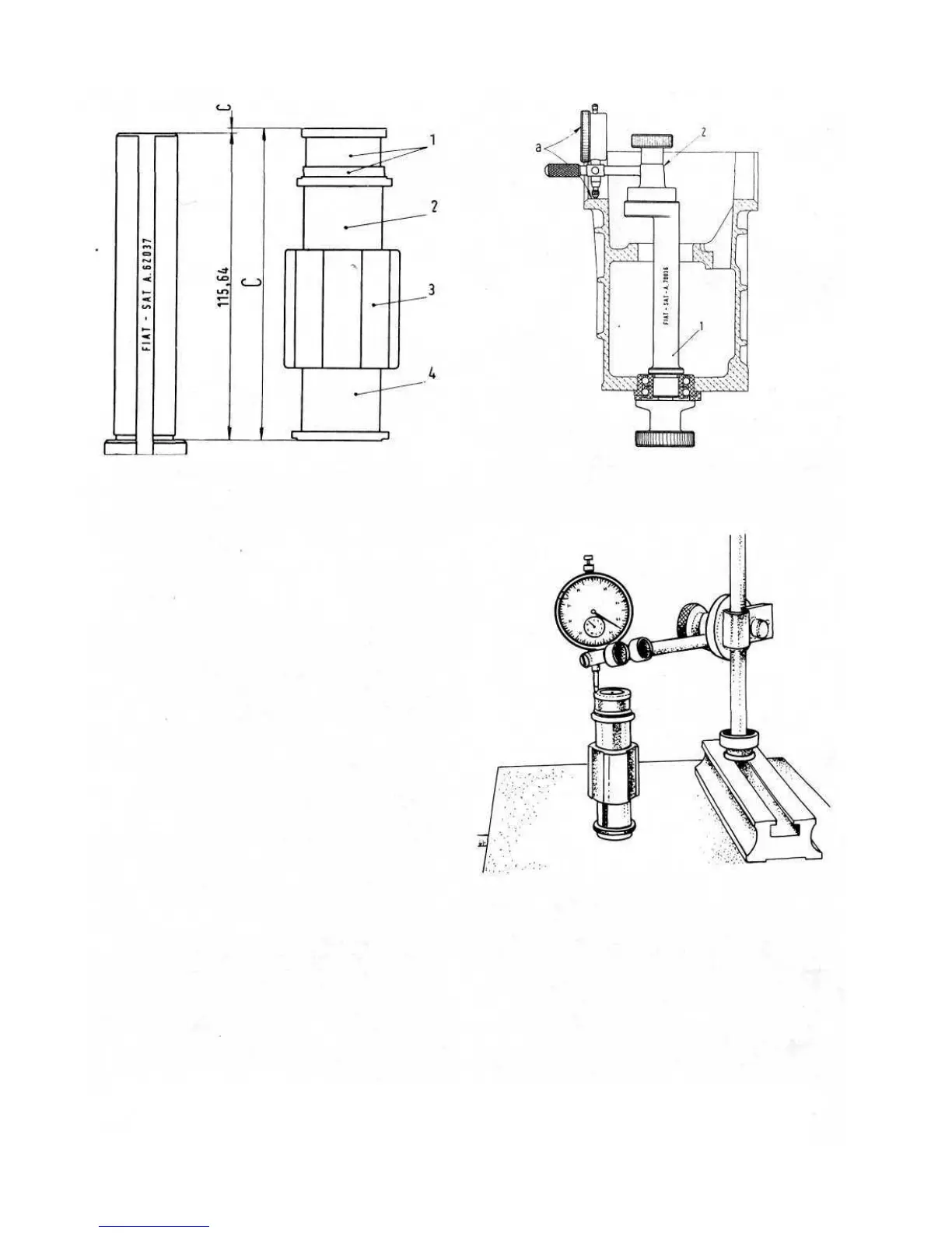
FIG 6:12 Graphic demonstration of C and c
Key to Fig 6:12 1 Bevel pinion rear roller bearing inner
race 2 Bush, fourth-speed driven gear 3 Hub,
third- and fourth-speed engagement sleeve 4 Bush,
third-speed driven gear
'C Total height of items 1, 2, 3 and 4 which must be mounted
on final drive pinion
'c' Difference between actual height C and the minimum
drawing call-out 4.5527 inch represented by tool A.62037
that the new Fiat tools are used to determine shim thick-
ness as detailed below:
S = 0.90 + a — (b + c)
Where S = shim thickness
0.90 = standard coefficient
a = value of reading on the dial indicator
A.95690 applied to fixture A.70036 as
shown in FIG 6:13.
b = value stamped on pinion stem as shown in
FIG 6:8.
c= value read on the dial indicator corres-
ponding to the difference between height
of Tool A.70037 as shown in FIG 6:14,
and the sum of the thicknesses of the items
to be installed in pinion and included
between front bearing inner shoulder and
rear bearing outer shoulder.
Ring gear clearance and differential bearing pre-
load :
To enable the correct ring gear tooth clearance to be
ascertained use Fiat tool A.62039 together with a dial
gauge. The support for dial gauge should be fixed into
the two lower bolt holes of the flywheel housing and the
pointer of the dial gauge adjusted so that it is located
through the clutch shaft hole in the final drive housing
so resting on a ring gear tooth (see FIG 6:15). Then
proceed as follows:
1 During reassembly the differential bearing nuts should
not have been screwed fully home to the differential
F500
73
bearing outer races when installing into the final drive
unit. These should now be carefully screwed in until
they are in gentle contact with the bearing races.
2 Slide Fiat tool A.62040 over one of the drive shafts
and using Fiat tool A.62041 lock the drive shaft to
the differential housing thus preventing the drive
pinion from rotating.
3 Gently turn the drive shaft which should now be
locked to the ring gear and note the movement of the
dial gauge indicator. This will show the tooth clear-
ance. When the clearance is correctly adjusted the
FIG 6:14 Reading value c on dial indicator
Key to Fig 6:13 1 Dummy pinion, tool A.70036
2 Support with dial gauge, tool A.95690
FIG 6:13 Diagram showing the position of tools for
determining the value of a