1st AND 2nd SPEED
STRIKER ROD LOCK
ROLLER
1st AND 2nd SPEED
STRIKER ROD
3rd AND 4th SPEED
STRIKER ROD
3rd AND 4th SPEED
STRIKER ROD LOCK -
ROLLER
REVERSE STRIKER
ROD LOCK ROLLER
REVERSE
STRIKER ROD
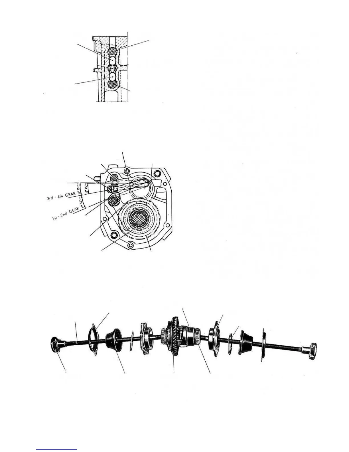
FIG 6:4 Detail of gearbox section through striker rod
lock rollers
2nd SPEED DRIVEN
GEAR
2nd SPEED ENGAGEMENT SLIDING SLEEVE
2nd SPEED FORK
1st AND 2nd
SPEED STRIKER ROD
REVERSE GEAR
3rd AND 4th
SPEED STRIKER ROD
REVERSE STRIKER ROD
2nd SPEED DRIVE GEAR
SPEED SELECTOR LEVER
FIG 6:5 Cross section of gearbox through striker rods
with the indication of the gear selector lever angular
displacement
68
AXLE SHAFT-TO-JOINT SLEEVE
OIL BOOT
RING GEAR
FIG 6:6 Differential unit complete with axle shafts
BEARING CONE
ADJUSTER LOCK RING
BEARING HOUSING
DIFFERENTIAL CASE
OIL BOOT RETAINER
AXLE SHAFT
1 Remove the speedometer drive support together with
its gears. Remove the front cover together with its
gasket and the gear selection rod (see FIG 6:2).
2 Remove the lock ring and carefully slide the splined
sleeve from the axle shafts. Remove the two roller
bearing housings together with the relevent rubber
boot fastening cover, the rubber boots and the adjuster
ring lock rings.
3 Detach the transmission mounting on engine support
and carefully remove the differential case assembly
complete with the ring gear and axle shafts.
4 Open the fasteners and loosen all the shifter fork lock
bolts.
5 Engage two gears at the same time so locking the
input shaft and the mainshaft together. Remove the
cotter pins and the nuts on the front end of the input
shaft and the mainshaft.
6 Remove the retaining cover located on the lefthand
side of the gearbox and carefully take out the shifter
rod positioning balls and springs from their bores.
Remove the upper shifter fork shaft and shifter fork,
the middle shifter fork shaft together with its interlock
pin and also the third and fourth gear shifter fork.
Remove the plain washer and speedometer drive
driving gear from the layshaft.
7 Remove the second gear engagement sliding sleeve
together with the shifter fork, shifter fork shaft, sliding
sleeve hub, second-speed driven gear with relevent
bush and the first gear engagement
fork. Take very
great care not to drop the safety rollers whilst extract-
ing the striker rods.
8 Remove the second-speed driving gear from the input
shaft. Release the reverse shaft retaining screw and
remove the shaft together with the reverse gear cluster.
Remove the layshaft front bearing retaining plate.
9 Push the input shaft forwards until both ballbearing
races are pressed from their seating and the coupling
sleeve located between the input shaft and the clutch
shaft can be reached from above. Carefully remove the
retaining ring and a connection pin at the input shaft
side of the coupling sleeve and carefully withdraw the
clutch shaft and coupling sleeve.
10 Remove the input shaft front bearing race. Tilt the
primary shaft in the casing and remove it from the
gearbox housing. Remove the rear bearing. Carefully