Reproduction forbidden without Fibocom Wireless Inc. written authorization - All Rights Reserved.
FIBOCOM L860-GL Series Hardware Guide Page 23 of 60
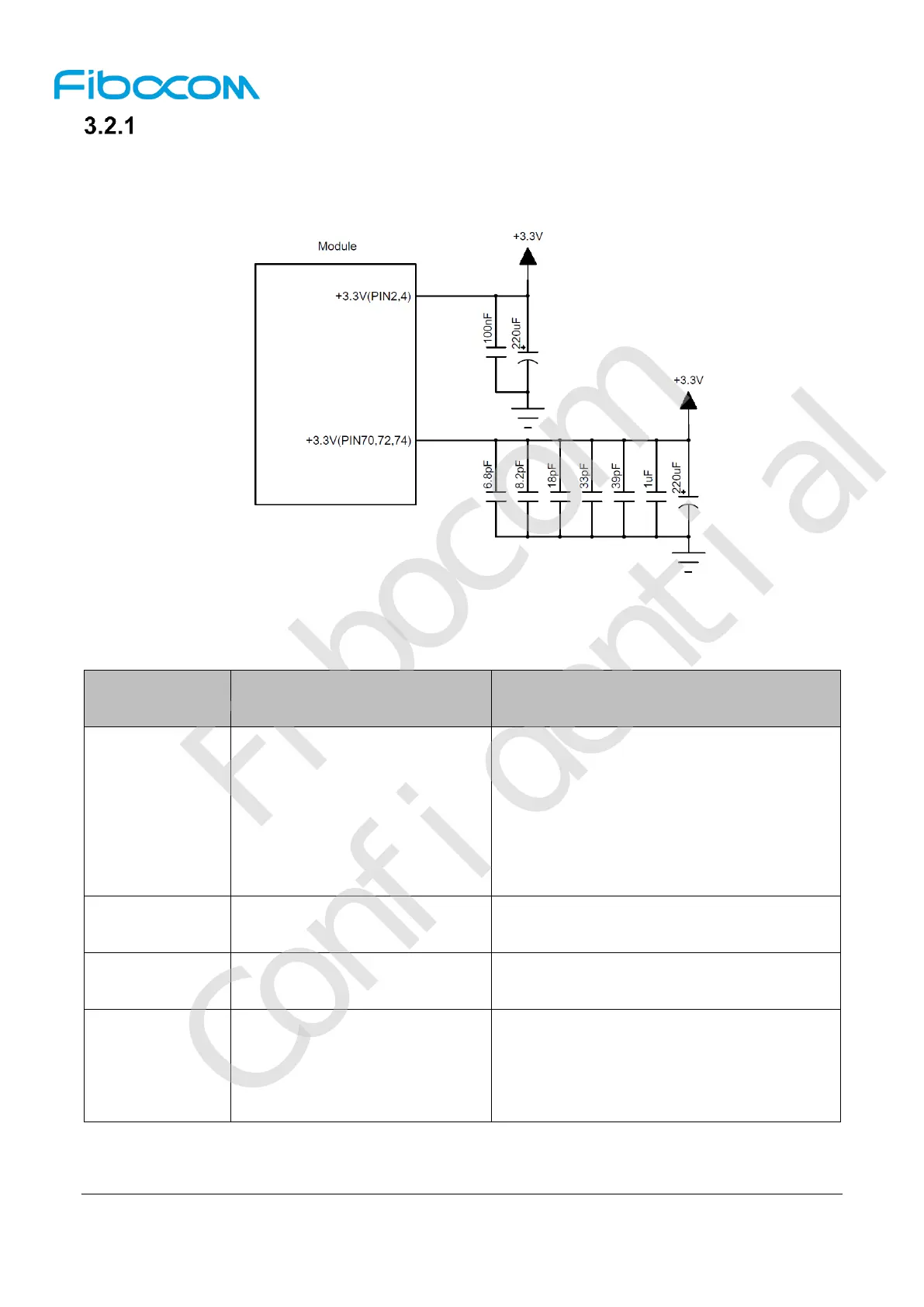
Power Supply
The L860 module should be powered through the +3.3V pins, and the power supply design is shown in
Figure 3-2:
Figure 3-2 Power supply design
The filter capacitor design for power supply is shown in the following table:
Voltage-stabilizing capacitors
Reduce power fluctuations of the module in
operation, requiring capacitors with low ESR.
LDO or DC/DC power supply requires the
capacitor of no less than 440uF
The capacitor for battery power supply
can be reduced to 100-200uF
Filter out the interference generated from the
clock and digital signals
700/800, 850/900 MHz frequency
band
Filter out low frequency band RF interference
18pF, 10pF,
8.2pF, 6.8pF,
3.3pF
1500/1700/1800/1900,
2100/2300, 2500/2600MHz,
3500/3700MHz, 5GHz frequency
band
Filter out medium/high frequency band RF
interference

 Loading...
