Reproduction forbidden without Fibocom Wireless Inc. written authorization - All Rights Reserved.
FIBOCOM L860-GL Series Hardware Guide Page 38 of 60
USIM1 Pins
The USIM1 pins description is shown in the following table:
USIM data, internal pull up (4.7KΩ)
USIM card detect, internal 390K pull-up.
Active high, and high level indicates SIM
card is inserted; and low level indicates
SIM card is detached.
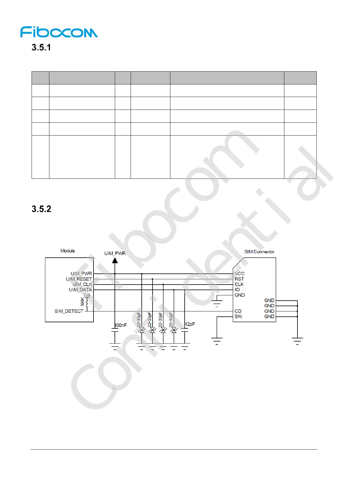
USIM Interface Circuit
3.5.2.1 N.C. SIM Card Slot
The reference circuit design for N.C. (Normally Closed) SIM card slot is shown in Figure 3-15:
Figure 3-15 Reference circuit for N.C. SIM card slot
The principles of the N.C.SIM card slot are described as follows:
When the SIM card is detached, it connects the short circuit between CD and SW pins, and drives
the SIM_DETECT pin low.
When the SIM card is inserted, it connects an open circuit between CD and SW pins, and drives the
SIM_DETECT pin high.

 Loading...
