EPACO USER’S MANUAL
Release Date: January, 2010 P/N: E06-091 (Rev 0) Page: 9
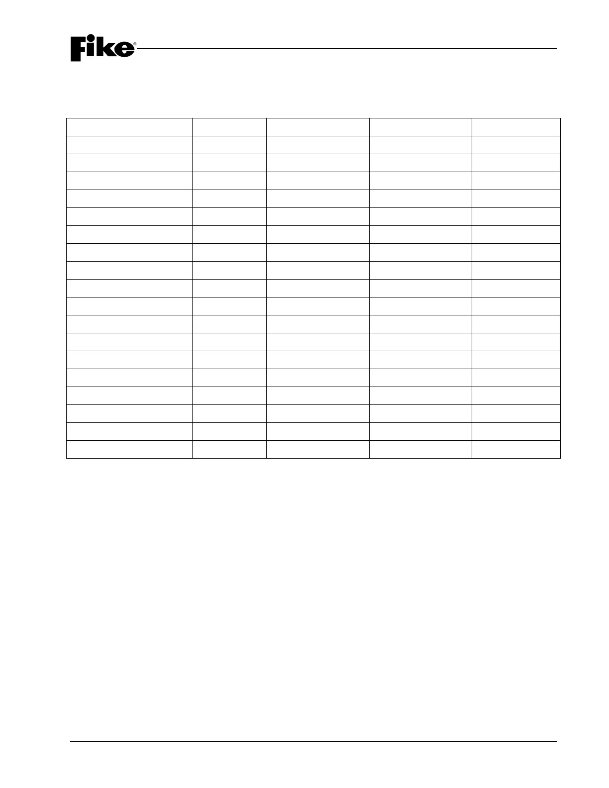
2.2.2 PSU DIAGNOSTICS
The PSU is equipped with four (4) diagnostic LEDs. The following table identifies how the LEDs will operate
in response to expected system events.
Status 25VAC Output Voltage 24VDC Battery Trouble
Normal Status GREEN GREEN GREEN OFF
Normal AC Power GREEN n/a n/a n/a
No AC Power OFF n/a n/a ON
Low AC Power RED n/a n/a ON
High AC Power RED BLINK n/a n/a ON
Normal Battery Power n/a n/a GREEN n/a
No Battery n/a n/a OFF ON
Battery off n/a n/a RED ON
Battery Shutdown n/a n/a RED ON
Battery Low n/a n/a GREEN BLINK ON
Battery High n/a n/a RED BLINK ON
Normal Charge Power n/a n/a n/a n/a
Charger Power Fail n/a n/a RED ON
Normal Output Power n/a GREEN n/a n/a
Low Output Power n/a GREEN BLINK n/a ON
High Output Power n/a RED n/a ON
Fan Trouble n/a n/a n/a BLINK
Ground Fault n/a n/a n/a ON
LNote: Trouble Relay is energized when Trouble LED is OFF, except when Trouble LED is blinking.
LNote: LED status for items marked “n/a” are not critical to defining that operation status.