EPACO USER’S MANUAL
Release Date: January, 2010 P/N: E06-091 (Rev 0) Page: 5
2.1.1 OPERATION
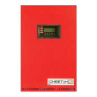
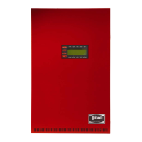
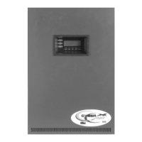
The EPC is equipped with three (3) colored LEDs that provide instant visual indication of system status. EPC
operation can be classified into three main states: Normal, Trouble and Alarm. A general description of each
state is described below.
EPC Normal State
When power is applied to the EPC, it performs a 4 second initialization. At the
end of the initialization, the trouble LED blinks slow and the local piezo beeps in
long recurring sound. It can then enter the “NORMAL” state if the power is of an
appropriate voltage and there are no troubles or alarms. In the Normal State the
green Power LED is ‘ON’, the local piezo is ‘OFF’, the trouble and alarm relays
are energized. All other LED’s are ‘OFF’.
EPC Trouble State
A trouble occurs on the EPC if any one of the supervised circuits experiences a
wiring fault open or short condition, if the EPC configuration is invalid, if the
system is disabled, if a process pressure warning level is exceeded, or if the input
voltage drops below 18VDC. In the Trouble State the yellow Trouble LED is ‘ON’,
the local piezo is ‘ON’, and the P6 trouble relay is de-energized. Depending on
the cause of the trouble, the system may or may NOT be completely functional.
Each trouble should be investigated to determine the cause and promptly fixed.
Each trouble, except for remote disable, will latch at the EPC. If the trouble is
resolved, the EPC trouble can be cleared by disabling and re-enabling via the
remote disable input, by cycling of the power input to the EPC, or by disabling
and re-enabling the EPC via the Annunciator Module. If the remote disable is
active, the EPC will enter the trouble state. When the remote disable is returned
to normal, the EPC will automatically clear to the normal state, if no other troubles
are present, without cycling the power.
EPC Alarm State
When the detection circuits have exceeded the alarm conditions required by the
configuration, the EPC enters the Alarm State. In the Alarm State the red Alarm
LED is ‘ON’, the local piezo ‘ON’, the Alarm relay is de-energized, and the series
firing output is activated. The alarm state is latching. If the alarm is cleared, the
EPC requires cycling of the power input to clear the alarm.
Red
24VDC
Green
Yellow