EPACO USER’S MANUAL
Release Date: January, 2010 P/N: E06-091 (Rev 0) Page: 15
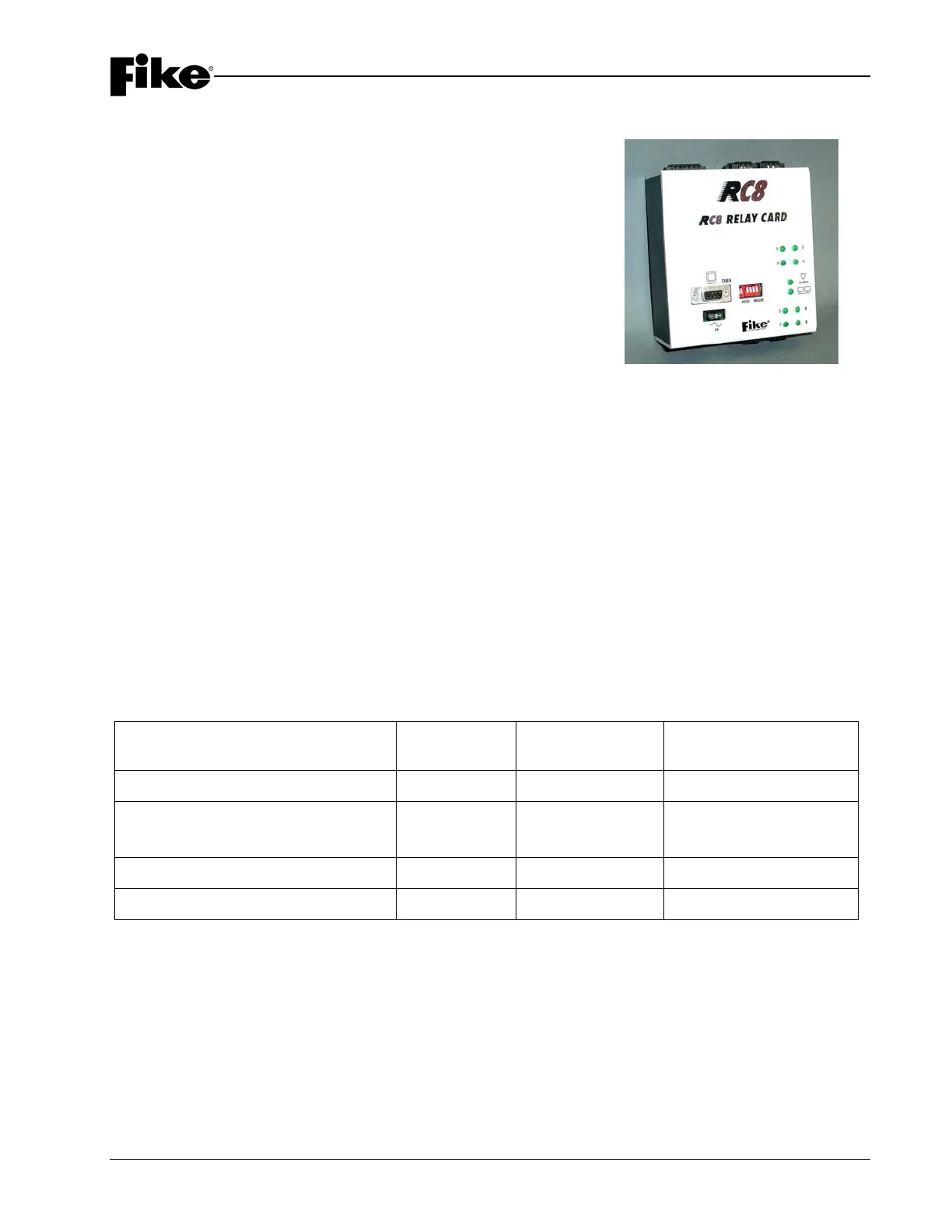
2.4 RELAY CARD MODULE
The Relay Card Module (RC8) provides the user with a block of
eight (8) fully programmable Form “C” relays. DIP switches are
provided for configuring the relay’s operation. These relays
facilitate process shutdowns or other actions in response to
conditions recognized by the EPACO system. Each relay is
equipped with a green LED to provide visual indication of the
relay state.
The RC8 is powered with 24VDC from the PSU. Up to four (4)
RC8s can be connected in parallel to the power supply. The
RC8 is capable of communicating on the Status Bus for
exchanging status information and remote control of the outputs.
A history of the relay states is captured in the Annunciator
Module
2.4.1 OPERATION
The RC8 is a fully programmable module. System configuration can be performed with DIP switches on
these modules or by way of a DB9 serial port connection to a PC using EPWorks™ Software. RC8
addressing is done using the two ADD (address) DIP switches. The four MODE DIP switches are used for
programming specific relay configurations. Expanded programming may be created via PC with Fike's
EPWorks™ Software.
The RC8 is a process interface for the EPACO system. The following tasks are accomplished by the RC8:
Communicates system status via relays for user interface
Direct shut downs, slow downs, and remote notifications of system trouble and alarm conditions
Remote location of interface, separate from the hazard zone
The RC8 operation can be classified into two main states of operation: Normal and Trouble / Alarm.
2.4.2 RC8 LED DIAGNOSTICS
Condition Power LED Status Bus LED
Relay LED(s) based on
Configuration
Initial power up [first 15 seconds] on off all off
Normal Sate
(No troubles or alarms)
on on all on
Invalid configuration on fast pulse all off
Trouble or Alarm on on corresponding off (1)
(1) Relay follows LED condition.