EPACO USER’S MANUAL
Release Date: January, 2010 P/N: E06-091 (Rev 0) Page: 13
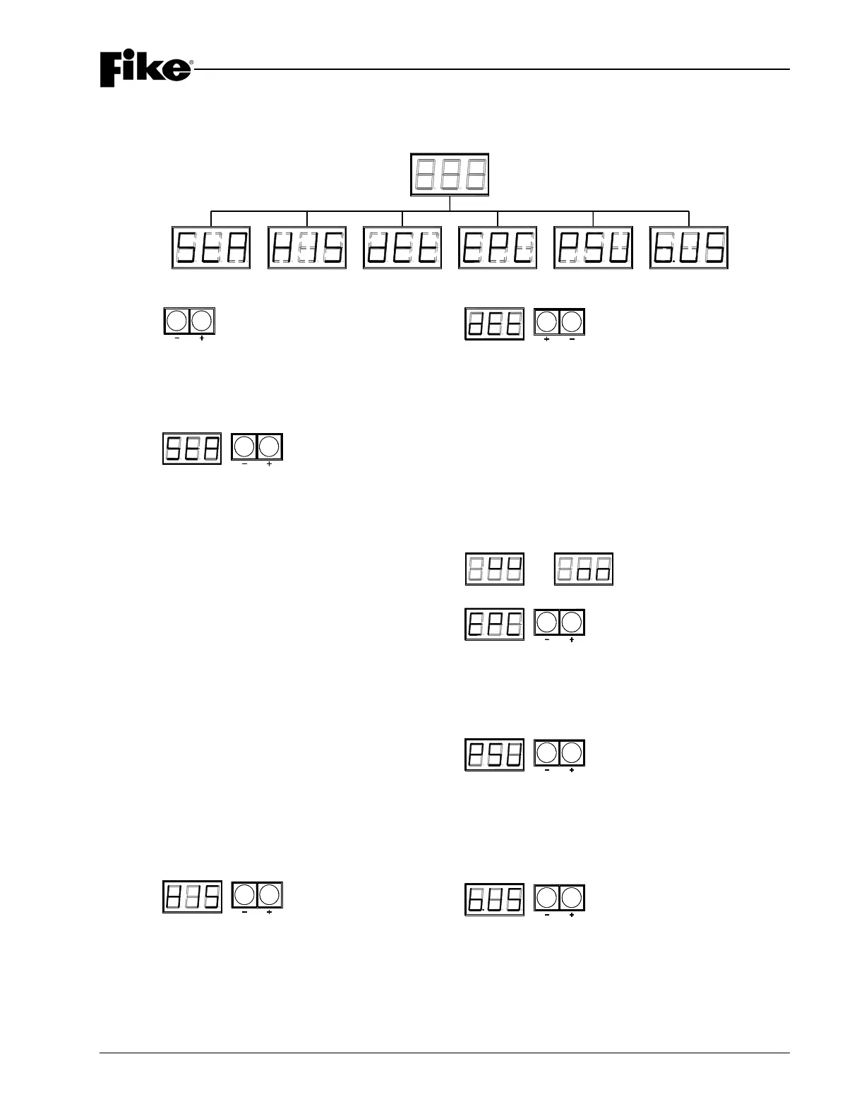
ANNUNCIATOR MODULE OPERATING MODES
Main Menu
Status
History Detector
Controller
Power
Supply
BUS
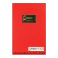
STATUS
Status
Left Button (-): scrolls to next module
Right Button (+): scrolls to previous module
Annunciator Module
0 0 1 Normal Status Bus
0 0 2 Module Trouble on Status Bus
0 0 3 EP System on Status Bus Activated
0 0 4 Communication Failure on Status Bus
005PC Mode
Explosion Protection Controller (EPC) X = EPC 1 to 4
X - - No EPC or EPC Shutdown
X 0 1 Normal Operation Mode
X 0 2 Trouble on one of the Input Circuits
X 0 3 Pressure Warning Level Exceeded
X 0 4 Trouble on one of the Output Circuits
X 0 5 Trouble on the Fire Bus
X 0 6 Predischarge Condition Satisfied
X 0 7 Supervisory Input Active
X 0 8 EPC has Activated Releasing Outputs
X 0 9 EPC has been Disabled
X 1 0 Failure during Arming
Relay Card (RC8) X = RC8 5 to 8
XYYY = Relay status
Refer to Appendix A for relay card status codes.
Power Supply Unit (PSU)
9 - - No PSU or No Communications
9 0 1 Normal Operation
9 0 2 Fan Trouble
9 0 3 Ground Fault Trouble
9 0 4 Battery or Charge Trouble
905 AC Trouble
9 0 6 Battery Backup being Utilized
9 0 7 Output Trouble
9 0 8 Outputs Disabled
9 0 9 Shutdown Mode
Navigation
Display current Operating Mode:
Momentarily press both switches
Menu Mode:
Press and hold both switches for 5 seconds
Left Button (-): Scroll menu options
Right Button (+): Select desired option
Menu Mode Timeout: 20 seconds of inactivity
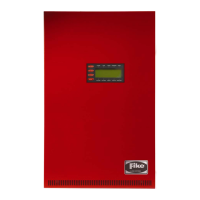
History
Displays 40 most recent events
Refer to Appendix B for listing of History Codes
Left Button (-): scrolls to older events
Right Button (+): scrolls to newer events
Pressing both buttons moves to the top of the file
Three lines across top of LEDs indicates Top of File (most recent)
Three lines across bottom of LEDs indicates Bottom of File
Pressure Detector
X X = Pressure Reading in Hex
Left Button (-): scrolls backward
Right Button (+): scrolls forward
1 X X EPC #1, Detection Circuit #1
2 X X EPC #1, Detection Circuit #2
3 X X EPC #2, Detection Circuit #1
4 X X EPC #2, Detection Circuit #2
5 X X EPC #3, Detection Circuit #1
6 X X EPC #3, Detection Circuit #2
7 X X EPC #4, Detection Circuit #1
8 X X EPC #4, Detection Circuit #2
6 2 -1.00 psig (-69 mbarg)
7 F 0.00 psig (0 mbarg)
8 D 0.49 psig (33 mbarg)
9 4 0.72 psig (50 mbarg)
9 C 0.99 psig (68 mbarg)
Refer to Appendix C for additional values.
Enabled/On Disabled/Off
Explosion Protection Controller (EPC) X X = Enabled/Disabled
Left Button (-): scroll EPC selection
Right Button (+): toggle EPC state
1XXEPC #1
2XXEPC #2
3XXEPC #3
4XXEPC #4
Power Supply Unit (PSU) X X = On/Off
Left Button (-): scroll PSU device selection
Right Button (+): toggle PSU state
1 X X Output #1
2 X X Output #2
3 X X Output #3
4 X X Output #4
5 X X Output #5
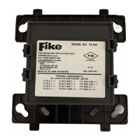
Bus Status
Used for engineering diagnostics.
Call Fike for support.