Quadnet Control Panel Engineering and Commissioning Manual
Loop Card Serial Port
The serial port may be used for connection to a computer running the Diagnostic software in order to
interrogate the loop communications; it is also used to upgrade the firmware of the loop card.
Loop Card Firmware Upgrade Link Pins
The loop card firmware may be upgraded on site using the external flash utility. The link pin should be left
connected for correct field operation and removed for firmware upgrade.
Note that firmware upgrades are only permitted to be carried out by Fike engineers or trained installation
engineers operating under specific instructions from Fike Technical Support.
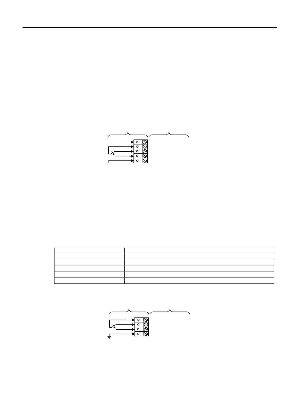
Outputs 1 and 2: SPR, COM, NC, NO, SCRN
Outputs 1 and 2 are derived from single pole change over ‘volt-free’ relay contacts which are not fault
monitored. The relay contacts are rated at 30V DC / 1A max. All inductive loads should be diode protected
to prevent back EMF. However, if this is not done, the load should be limited to 200mA to reduce the
likelihood of back EMF causing damage to the relay contacts.
The default setting for Output 1 causes the relay to operate as a Common Fire output where the relay is
energised in the fire condition. The default setting for output 2 causes the relay to operate as a Common
Fault output where the relay is de-energised in the fault condition. Various other modes may also be set
using the Quadnet OSP programming software. However, to meet the requirements of EN54-2, Output 1
must be left as a fire output (Common Fire or Zonal Fire) and Output 2 must be left as Common Fault.
On later versions of the panel hardware, Output 2 is optimised for Common Fault use and has an additional
safety feature (which cannot be disabled) to turn off the output in the unlikely event of the operating
software stopping, even if not specifically configured as Common Fault.
Spare terminal for general use. Not connected internally.
Field cable screen connection
Outputs 3 and 4: COM, NC, NO, SCRN
Outputs 3 and 4 are single pole change over ‘volt-free’ relay contacts which are not fault monitored. The
relay contacts are rated at 30V DC / 1A max. All inductive loads should be diode protected to prevent back
EMF. However, if this is not done, the load should be limited to 200mA to reduce the likelihood of back EMF
causing damage to the relay contacts.
The default setting for Output 3 and Output 4 is “not configured”. Various modes may be set using the
Quadnet OSP programming software.