Quadnet Control Panel Engineering and Commissioning Manual
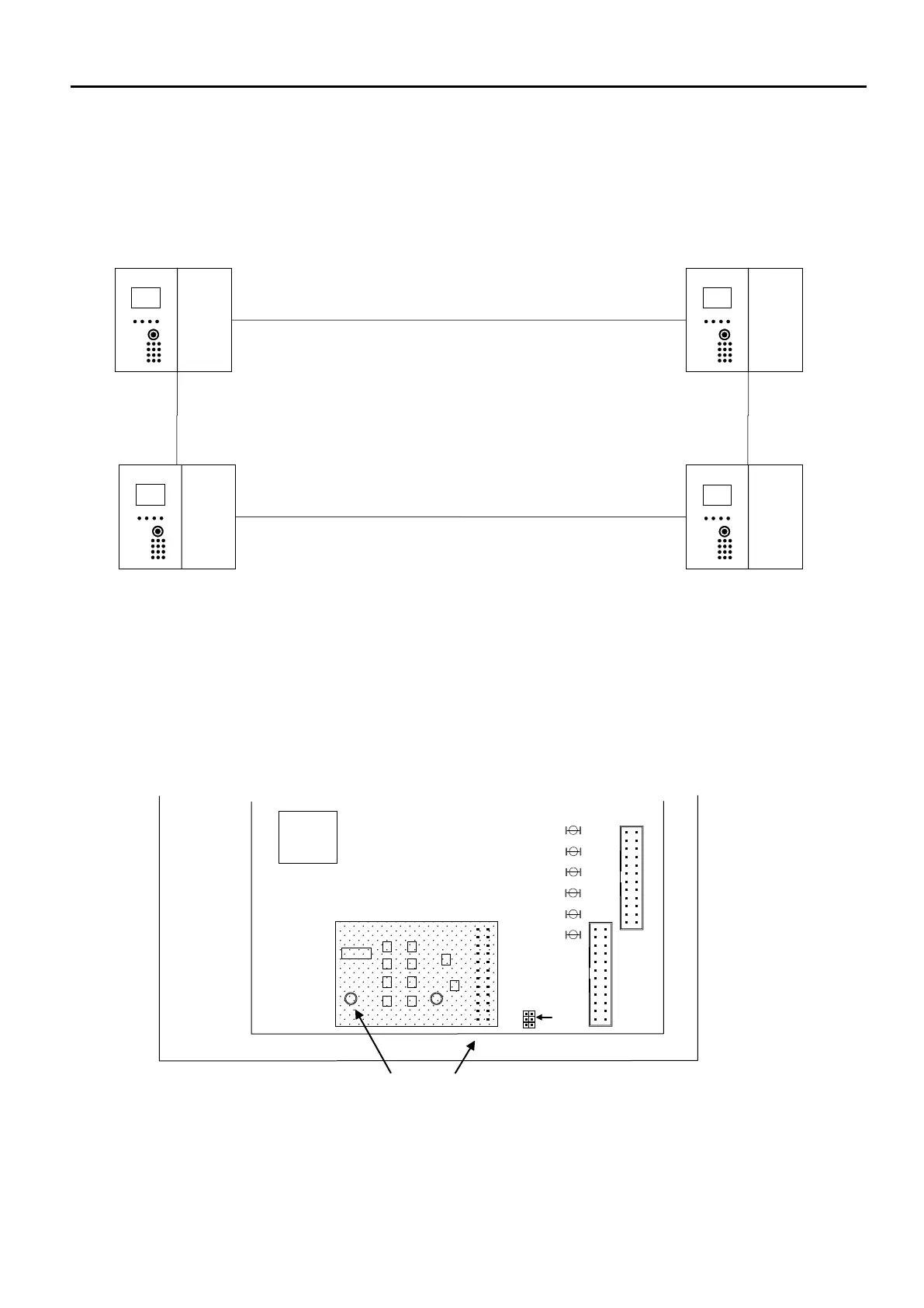
Network Connection Schematic
As shown above, the numbering of panels may be in any order. However, when planning an installation, it would
make sense to number the panels sequentially in the order in which they are wired. The maximum number of
networked units is 4. These can be a mixture of repeater panels and control panels.
Network Terminals
Before any networking facilities may be used, the optional Quadnet network card must be fitted to the control panel
main PCB (CIE) as shown above.
Network cabling connects to the Network terminals on the backplane PCB.
All network cables should be 2-core 1.5mm
2
screened and fire-rated.
The 2 Network Ports (NET1-2) may be connected in any sequence.
TO TERMINATION PCB
MAIN
PROCESSOR
DO NOT CONNECT
CONTROL PANEL MAIN PCB (Located on the inside of the front left hand inner door)