Quadnet Control Panel Engineering and Commissioning Manual
Control Panel Terminals
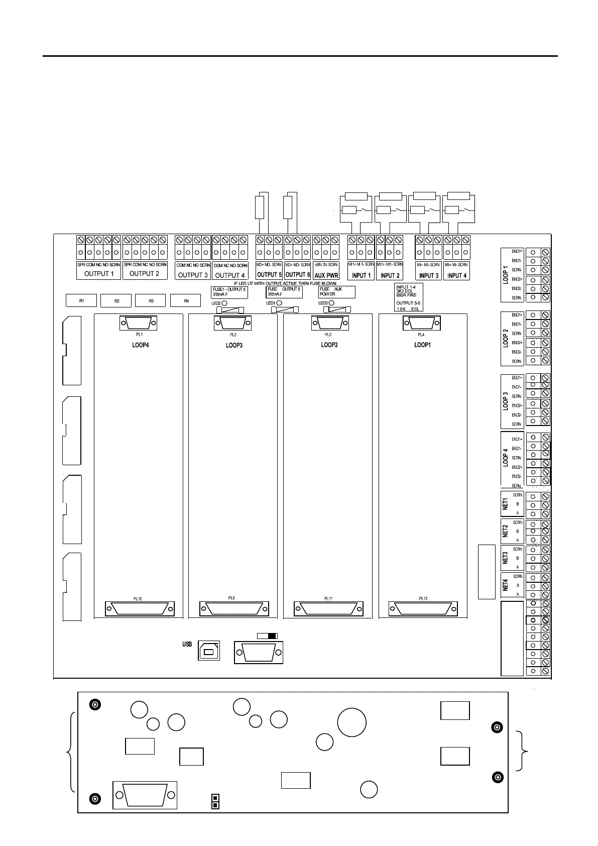
The Termination and PSU PCB (also known as the backplane) is located at the rear of the main control
panel back box.
The Loop cards may be plugged into the loop card slots on the backplane. To avoid damage, ensure that
the panel is powered down whilst connecting and removing the loop cards. When connecting, do not
press down on the loop card other than where indicated. Similarly, when removing, do not pull the centre of
the card but pull from both ends at the same time so that the PCB does not get flexed.
o o o o o o o o o o
o o o o
BUFFER
BUFFER
ONLY
PRESS HERE ONLY
RIBBON CABLE CONNECTIONS TO MAIN CONTROL PCB MOUNTED ON DOOR
BACK PLANE CONNECTION PCB
SCRN
B
A
SCRN
0V
+24V
SCRN
0V
+24V
O
T
U
S
E