Quadnet Control Panel Engineering and Commissioning Manual
Initialisation
Normal Readings
Ensure that your addressable device loop has the correct continuity and insulation integrity. With an
electronic test meter there should be a continuity reading of approximately 1.2 ohms per 100m of 1.5mm
2
cable, and no continuity should be read between cores.
With the loop stopped and the loop connector block removed from the control panel, measure the continuity
between Loop End 1 –ve and Loop End 2 –ve. There should be a maximum resistance of approximately
24 ohms, equating to approximately 1.2 ohms per 100 metres.
Likewise measure the continuity between Loop End 1 Scrn and Loop End 2 Scrn. There should be a
maximum resistance of approximately 24 ohms, and this reading will normally be slightly lower than that of
the Loop –ve continuity, due to the greater surface area of the screen. Screen integrity is of critical
importance.
A measurement of the continuity between Loop End 1 +ve and Loop End 2 +ve should show a very high
resistance, as the isolator within each device only provides continuity when energised by the control panel.
Measuring the insulation resistance between the Loop –ve and the Loop Screen should show no
continuity. Remember that a low voltage electronic test meter should be used, and its accuracy is likely to
be low when measuring high resistances, but this will give enough information to show insulation integrity.
Do not use a high voltage insulation test meter whilst any devices or the control panel are
connected as they will suffer damage.
Initialisation Process
When the control panel is powered up the following LEDs will be continuously on, and the addressable
device loop must be initialised at Access Level 3 (Engineer).
DISABLED and LOOP FAULT/DISABLED
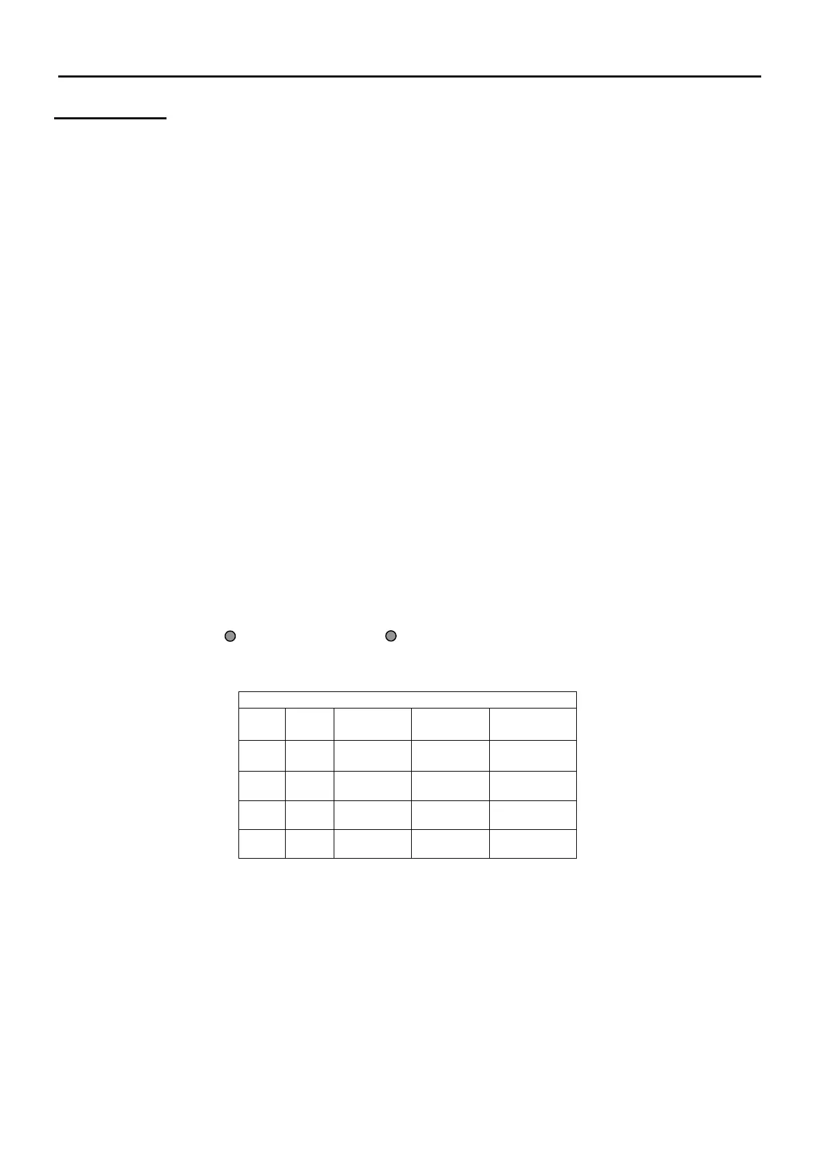
During initialisation, a screen similar to the following will be displayed.
The Loop Card status will be as follows:
ON Loop card assigned and present
NO Loop card not assigned
The number shown under Loop Dev Init gives a count of the number of devices initialised on the loop. If
the loop is found to be complete this is followed by a tick, whereas if the loop is found to be incomplete this
is followed by a cross.