Quadnet Control Panel Engineering and Commissioning Manual
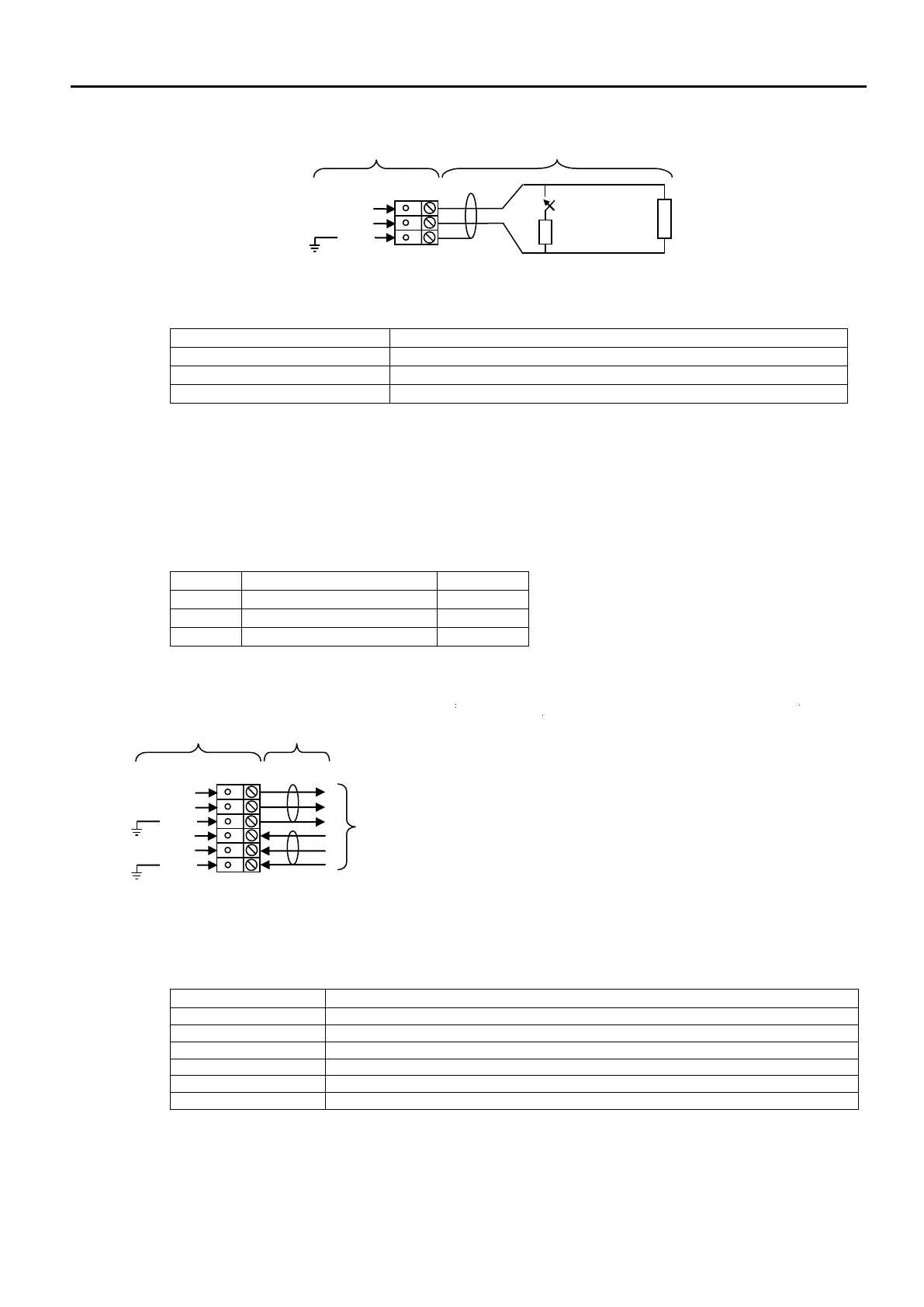
Inputs 1- 4: MI+, MI-, SCRN
Inputs 1-4 may be configured to monitor for open and short circuit faults using a 3k3 EOL resistor, and to
activate an alarm link using a 680R ‘firing’ resistor.
Monitored Input positive connection
Monitored Input 0V connection
Field cable screen connection
Fuses 1-3: FUSE 1, FUSE 2, FUSE 3
The fuses are located towards the top of the back plane PCB.
Blown fuses are easy to spot using the LED adjacent to each fuse. This will switch on if the output is
switched on (even in the passive state) and the fuse is blown.
Addressable Circuit Loops 1- 4: END1+, END 1-, SCRN, END2+, END2-, SCRN
Each loop 1-4 addressable circuits must be connected to its
appropriate End 1 and End 2 terminals.
Communications normally run from Loop End 1 but, in the event of
a continuity fault, both ends of the circuit will operate.
It is important that the cable screen is only connected at the control panel (using the SCRN terminal
provided, not at any earthing point), and that the screen continuity is maintained at all times. 4-core cable
must not be used as a loop ‘feed & return’ due to the possibility of data corruption.
Circuit End 1 positive connection:
Circuit End 1 0V connection :
Field cable screen connection:
Circuit End 2 positive connection:
Circuit End 2 0V connection :
Field cable screen connection: