4-28
4.5.1-53 4.5.1-54
4.5.1-55 4.5.1-56
4.5.1-57 4.5.1-58
4.5.1-59 4.5.1-60
4.5.1-61
• Cut any eventual clamps that secure
the hose to the machine body.
• Remove the hose from the fitting.
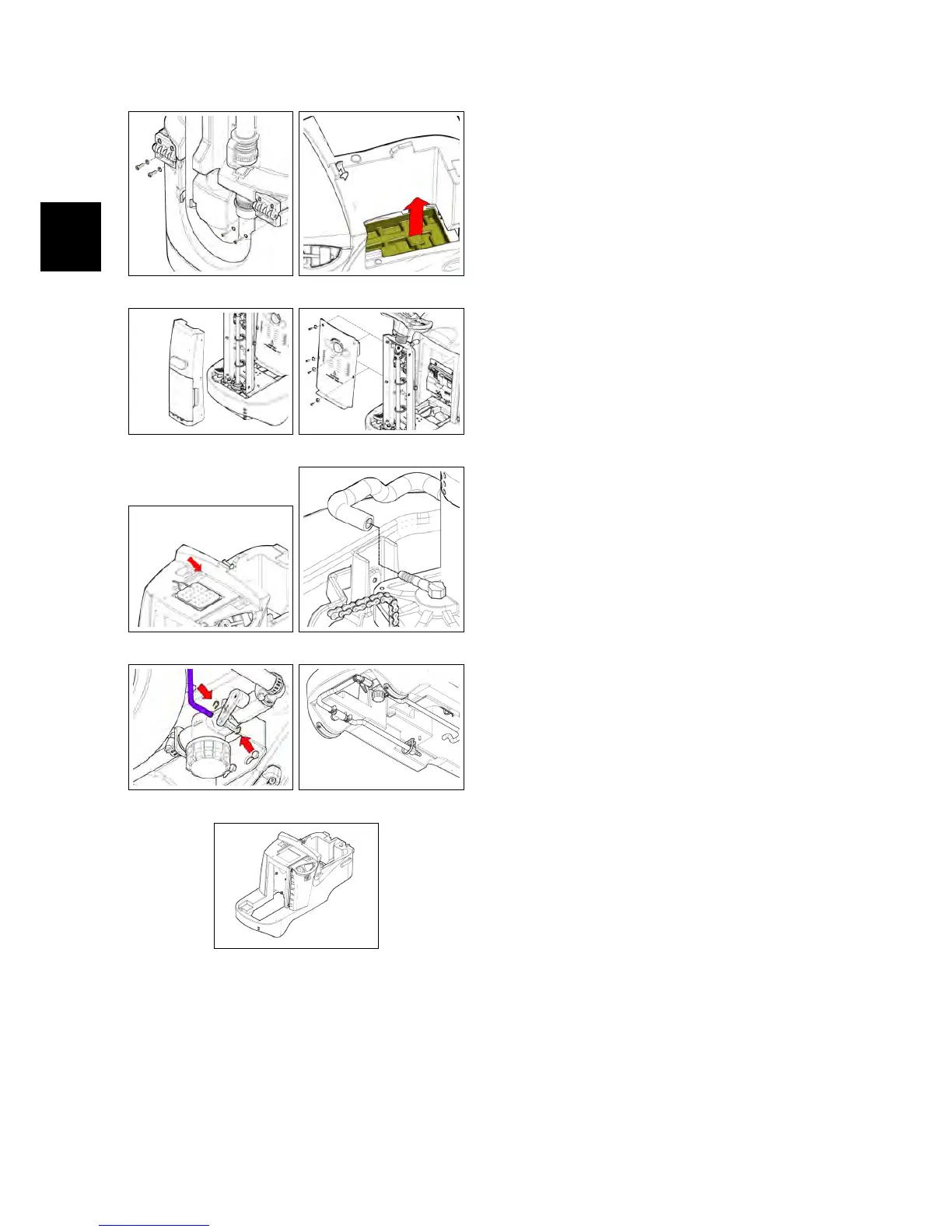
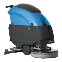
4.5.3 Water Valve/Solution Fil-
ter
• Put the machine in safe conditions.
• Disconnect the control rod from the
water valve (see fig. 4.5.3-62).
• Disconnect the hose from the fitting,
attached to the water valve (see fig. 4.5.3-
63).
• Disconnect the hose from the fitting
attached to the solution filter (see fig.
4.5.3-63).
• Loosen the screws that hold the sup-
port plate to the solution tank (see fig.
4.5.3-64).
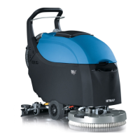
• Remove the group including the wa-
ter valve and the solution filter (see fig.
4.5.3-65).
• Unscrew the elbow fitting attached
to the water valve (see fig. 4.5.3-66).
• Unscrew the water valve from the
nipple fitting and remove it (see fig. 4.5.3-
67).
• Unscrew the nipple fitting from
the solution filter and unscrew the
straight fitting from the solution fil-
ter (see fig. 4.5.3-68).
• Remove the solution filter (see fig. 4.5.3-
68).
4.5.4 Solenoid Valve
• Put the machine in safe conditions.
• Remove the hoses connected to the
solenoid valve.
• Loosen the screw that secures the
solenoid connector and disconnect
the connector from the solenoid coil.
• Unscrew the plastic nut that secures
the solenoid valve to its support.